Hi so I made the SD card placed it into the SD slot connected the HDMI cable, a key board, the Switch (boot) in position 1 and then connected the power. Result Power led always on. Activity Led Always blinking. A Blue Led blinks now and again. And its stays that way. I have waited up to 30 minutes before turning of and I have tried many times.
Should would will mybe🤔
1 Like
Hi,
first of all here are two links for you that might give you a bit more info:
- Reference page: http://www.banana-pi.org/m4.html
- Wiki: http://wiki.banana-pi.org/Banana_Pi_BPI-M4
The later shows an image of the board, including for example the switch and buttons. While I not have an M4 board, I believe the switch only has a function if you use both, the eMMC on board memory and a SD-card, to tell the board from which to boot. The red led is for power, the second blue is user programmable and usually shows activity. If the blue led is on it usually mean the board powerd up and loaded the image correctly.
You may want to connect the PC via USB to the debug UART connector. For this you may need something like this:
Those kind of cables are invaluabe in every Pi project. For the 4-wire one you usually leave the red power one unattached. On the client (PC) side I usually go with putty, see this howto video.
Some further questions:
- Which exact image did you burn to your SD card?
- Which SD card do you use?
- Which program did you use to burn the image?
- What did you connect to the HDMI port, a regular monitor or an LCD screen?
Hi Now were to start: The Reference page: Reference page: http://www.banana-pi.org/m4.html 1
And the Wiki: http://wiki.banana-pi.org/Banana_Pi_BPI-M4 1
I have read and copied most of it to my hdrive. It has no information about what the “Boot switch” does neither does it say anything about the two buttons “Install” and “Boot” do. I understand the red and green Led´s the blue!
Images I have tried.
Linux Ubuntu.
Google Drive : https://drive.google.com/open?id=1nPI2dy_KCW4h5korQdvj0iymHIDyxIPq
Linux Debian.
Google Drive : https://drive.google.com/open?id=1rVrZStsw2PINBhIxCzOLOtYLbtoECmEk
Android.
Google Drive:https://drive.google.com/open?id=12wB3CqGBDxE7Cyi_BzZbAid0UlZCtcFZ
So, what happens I made the SD card placed it into the SD slot connected the HDMI cable, a key board, the Switch (boot) in position 1 and then connected the power. Result Power led (red) always on. Activity Led (green) Always blinking. A Blue Led blinks now and again. And its stays that way. I have waited up to 30 minutes before turning of and I have tried many times.
Questions is the flash empty from the factory. Just turning on the card should I see anything on the display. Do I have to press the “Boot” button after loading an image? How do I know when the image is loaded? If you open the Android zip file is says information about using a “hypertrm.exe” and a serial port what a joke, hypertrm died with windows XP and a serial port? I only have USB.
Hi,
so for Linux Ubuntu you essentially tried this one:
which @spikerguy proposed and should be Ok to get you started.
The FAQ on the page indicate that if you have trouble with the HDMI display you should try:
- [CTRL] + [ALT] + [F1] which will essentially drop you to the console login (or F2…F6)
- [CTRL] + [ALT] + [F7] which should switch you back to the graphical desktop
The boot switch set to position 0 will start the SD card, and fallback to internal eMMC if no SD card is found.
And yes, by default the eMMC flash is empty and you have to first start with a SD card that is burned with an Image. After it is loaded you then can copy over whatever distro you like to the internal eMMC. A regular Rasperberry Pi only comes with SD card.
For burning the image to the SD card I would use something like balenaEtcher as @spikerguy suggested.
Starting with an SD card slotted in, you should see an output on your screen of the Linux operating system starting up, printing out things like (this is for an M64 board, but there shoud be some console output similar):
...
[    0.000000] Linux version 4.4.89-BPI-M64-Kernel (root@JackBpi) (gcc version 4.9.3 20150113 (prerelease) (Linaro GCC 4.9-2015.01-3) ) # 8 SMP PREEMPT Thu Nov 1 15:46:06 CST 2018
...
[    0.000000] Kernel command line: board=bpi-m64 console=earlyprintk=sunnxi-uqt,0x01c28000 console=tty1 console=ttyS0,115200n8 no_console_suspend consoleblank=0 root=/dev/mmcblk0p2 rootfstype=ext4 rw rootwait bootmenutimeout=10 datadev=mmcblk0p2 service=linux4.4 bpiuser=720p mac_addr= enforcing=1 initcall_debug=0 loglevel=8 init=/sbin/init cma=256M panic=10 fsck.mode=force fsck.repair=yes disp.screen0_output_type=3 disp.screen0_output_mode=5 disp.screen1_output_type=3 disp.screen1_output_mode=5 androidboot.serialno=8417***********0a0f boot_type=1
...
[    0.180062] Brought up 4 CPUs
[    0.180284] SMP: Total of 4 processors activated.
[    0.180310] CPU: All CPU(s) started at EL1
[    0.180350] alternatives: patching kernel code
[    0.180515] Invalid sched_group_energy for CPU3
[    0.180540] CPU3: update max cpu_capacity 1024
[    0.180544] Invalid sched_group_energy for CPU2
[    0.180583] Invalid sched_group_energy for CPU1
[    0.180604] Invalid sched_group_energy for CPU0
...
However not all displays and screen resolutions are supported which could be one reason why your screen may stay black. On contrary at least on the UART console you should see something. If nothing shoes up on the UART console you may need to reverse Rx and Tx cables on the pins.
Normally when you can see the ‘blue’ heartbeat led you know your kernel is fully loaded.
I understand that you may be frustrated but when dealing with any Pi, then you are tinkering on a hardware low level. Before one can use USB or any other functionality a driver has to be loaded and configured, while serial communication is usually provided as is. You essentially going back to the roots. The suggested ‘hypertem.exe’ is just a terminal program to connect to the UART serial console pins, for which I suggested to use PUTTY as a successor instead.
So if there is a problem, one usually grabs an USB to serial connector (UART) cable as linked before to see what is or what is not going on.
The Banana Pi do indeed have a steeper learning curve then a regular Raspberry Pi.
PS: regarding the buttons, the one labeled ‘boot’ is I guess actually the ‘reset’ button. The ‘install’ button is I guess supposed to help you copy over an SD card to the internal eMMC but was indeed never oficially documented. I do not have an M4 board at hand so I can not test it myself.
Independent of that, you should normally not need to press a button to start your board as it should start up as soon as it gets power.
Thanks, I have some thing to go on Ill let you know how things turn out.
Hi I connected the BPI-M4 (Not M64) to my tv set through the HDMI display output the only display out put on the board, couldn´t try the [CTRL] + [ALT] + [F1] or the [CTRL] + [ALT] + [F7] because the USB ports aren’t enabled until the flashing process is complete because as you said the flash is empty from the start. But when the blue led started to blink, I could see a Linux OS on the TV screen. Now how do I put the OS into the eMMC “Copy”.
Next, I tried the Android set up and this can’t be correct.
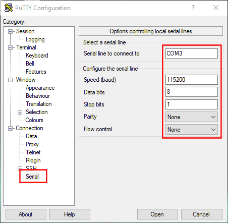
“1.2 Set Baud rate: 115200, data bit: 8 bit, stop bit: 1 bit, Parity: NONE, Flow control: NONE”
I have installed Putty, tera term and even hypertrm and played with Baud rate data bits etc. I have contact with the board but nothing like, the display is what you image if the connection is wrong.
And btw The Banana Pi does indeed have a steeper learning curve then a regular Raspberry Pi. but that is mainly because the document is so, you couldn’t say bad because there isn’t any it´s a question of looking at the drawings and going over the schematics and doing some guest work but even then you need some basic information or is this board so new there isn’t any!
1 Like
Usb is enabled as soon as the device is powered on. Can you explain how did you flash this image BPI-M4/BPI-W2 Demo Image Release : Ubuntu Mate 18.04 & Ubuntu Server 16.04 2019-06-18 to SD Card? This you use the MATE version or the SERVER version?
It would be helpful for us to understand your situation if you could provide a short video of what you could see on the screen when you do the above method.
This will need a UART cable for you to connect it. This is the one I am using Link
To connect the cable see the following image:
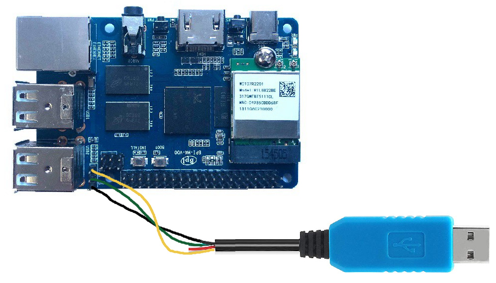
Keep the red wire (power/vcc) open, connect black to ground and the TX/RX lines usually have to be crossed (meaning Rx has to connect to TxUsb and Tx has to connect to RxUsb). If the crossing does not work, try to reverse them.
For how to configure putty have a look at this youtube video:
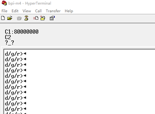
Having strange characters on the serial bus can either mean that you forgot to connect ground or that the settings for Baud/data/stop bit are wrong.
Some more pictures how to setup putty:
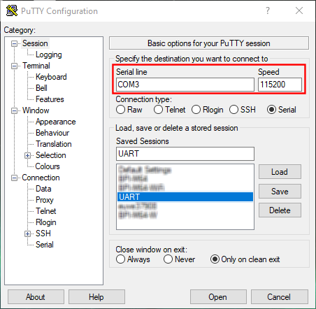
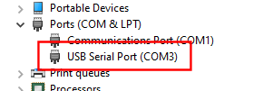
Make sure the com port is actually the same as reported in your windows device manager:
What putty version is this ? were can I down load it!
Forget that question
Here is the download like for Putty. You can use the latest version. https://www.chiark.greenend.org.uk/~sgtatham/putty/latest.html
Do you have a UART Cable to use it with ?
HI, I downloaded the schematics and that was a great help. I’ve got the m4 to load and run Linux Ubuntu Mate 18.04. bty a good pointer is that you can’t use a digital monitor even if you are using a HDMI to digital adaptor that was my first mistake, worked find with my APC, Raspberry and set box but not the BPI! I think I have some issues with the 3.3 V to TTL level so I can’t load Android at the moment, I have tried with a standard serial cable but that didn’t work neither did the uart cable I made. I’ve order a uart adaptor from internet. Now for the questions. 1. After I have booted up from the cd card how do I load the eMMC and how do I boot up from it. 2. The RTD 1395 can support NAND but I can’t see any on the board. 3. The “BOOT_SEL” pin B16 is that connected. 4. The “GPIO_48 and 49 come from “SW2” and “SW5” what function do they have and at the same time pin 52 “INSTALL” coming from” SW4” what function does that have. Well for now that’s it looking forward to the answers. BR
- Burn image to emmc, and switch SW2 on the side of SD card to “1” position, which starts from emmc
- Our M4 does not include nandflash circuit design, only emmc and SD
- BOOT_SEL is fixed when RTK leaves the factory and cannot be modified
- Functions of SW2 and SW5 are easy to understand from the schematic diagram
- SW4 is for system upgrade
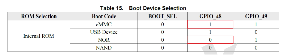
Hi now we’re getting somewhere. To burn the image from “NOR” to eMMC I’m going to have to get the bpi-tools not sure about the syntax. I noticed looking more at the schematics that the “BOOT_SEL” was hard coded also the doc on the Realtek has a lot of good information, btw can I connect to the composite video output in anyway. Br keith
Do you have an answer to the question about comp video?
Judging from the schematics
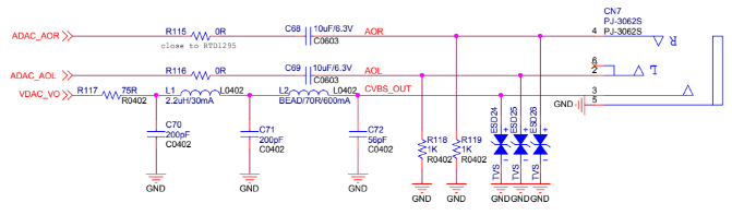
you will need an adapter cable that provide 3.5 Jack to RCA, to make use of composite video, but beware as there are several different standards/cable variations and you wnat one that looks like that:
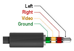
Additionally composit video output is different between PAL and NTSC so it is also a question to which kind of CRT you want to connect. Last but not least you probably want to disconnect the HDMI cable as I am almost certain that you can only use either one. Saying if the board detect an HDMI cable it will most likely disable composite video.