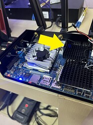
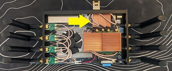
i originally had antennas from the be14 kit but they were horrible so i sent it back and brought different antenna kit from digikey (GW.52.A153), which Vader said was a really good antenna, i saw some improvement with it and used a rg178 20cm cable all the way round. and as for the power supply its a anker usb c 65w GaN charger. i dont get any random reboots and the charger right now is probably overkill since i dont even have an SFP stick yet
Try these WiFi settings on the 5 GHz band:
- Mode: AX or AC (do not use BE mode because the driver is not yet mature)
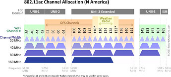
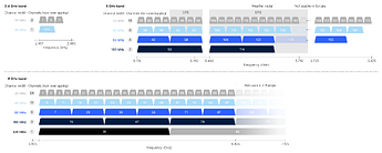
- Channel: 36 or 149
- Width: 40 MHz or 80 MHz (never use 160 MHz width in the 5 GHz band)
- Country Code: Guatemala [GT] or Japan [JP] or Panama [PA] or United States of America [US]
Watch this video:
If doing that doesn’t improve the speed then maybe the problem is in the mt76 driver or in your cell phone, in another post you mentioned that your cell phone is a Sony Xperia, this cell phone is niche and is not recommended.
Also try another cell phone model such as Google Pixel, iPhone or Samsung to see if the same problem occurs.
Will try this , thanks for trying to help
You can also start from scratch to configure the WiFi:
-
Regenerate wireless configuration
To rebuild the configuration file, e.g. after installing a new wireless driver, remove the existing wireless configuration (if any) and use the wifi config command:
rm -f /etc/config/wireless
wifi config
Ok a quick update on the situation, I use SFP copper wan now (only temporary till I move to full fibre) I’m starting to 5ghz albeit not at the same speed my isp router can do it it at which is 270mbps,.I’m getting somewhere between 33mbps to 80mbps which is a massive improvement over the previous speeds and not being able to connect at all, not sure what’s happened here, also can someone suggest a heatsink for the SFP since they get blistering hot
Maybe these copper heatsinks will help you, I think the dimensions of the heatsink should be 40x40x10mm for BPI-R4 and 35x35x11mm for BPI-R3, these heatsinks do not come with thermal pad or thermal tape, you need to buy it.
AliExpress Links:
Cooltex:
Cotexer:
.
40x40x10mm (BPI-R4)
35x35x11mm (BPI-R3)
Source:
- OpenWrt Support for Banana Pi BPI-R3 - #161 by tduffy83 - OpenWrt Forum
- My BPI R4 went DEAD - #1 by ljy26
.
P.S. Maybe these small heatsinks can also help you:
I’ve posted this on the OpenWrt forum, but this might be a better place. I noticed the SNR of 5 GHz clients one room away as seen on the router to be rather poor, which might be the root cause of coverage issues.
My old Archer C7 router shows the same signal strength for the clients, but noise level in the -100 dB range. Noise level on the BPI-R4 is -81 dB at best with Taoglas antennas and RG178 cables. I’d like to hear an expert opinion whether it’s normal to have such a high noise level and if this is something that can be improved by future drivers rather than a hardware flaw.I see the very same thing with stock antenna (the ones bundled on AliExpress with BananaPi): On the BananaPi I have a reported noise level of around -80 dBm on both bands (5G, 6G), while on my client (MacBook) it is in the -95 dBm range. So it looks like the noise level is quite high on the BananaPi.
You can try with the official Banana Pi firmware that uses “proprietary” drivers to see if the same problem occurs:
If the problem is solved when using Banana Pi firmware, it means that the culprit is MediaTek “open source” drivers, but if the problem occurs on both firmware (Banana Pi firmware with “proprietary” drivers and OpenWrt firmware with “open source” drivers), then the problem is in the Wifi 7 module design (BE14).
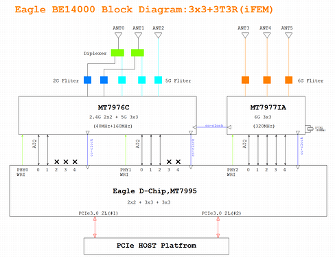
Remember that the BPI-R4 uses diplexer on the 2.4 GHz and 5 GHz bands (or radios), so both bands (or radios) use the same antennas, you can also try turning off the 2.4 GHz radio and only use the 5 GHz radio to see if this improves the SNR (Signal-to-Noise Ratio), this is the first time that Banana Pi uses diplexer and maybe it is poorly executed.
- Banana Pi BPI-R4-NIC-BE14 | BananaPi Docs
- Banana Pi BPI-R4 Wifi 7 Module design
- [BPI-R4] Which Wifi-Module version do you prefer?
.
What is the Signal-to-Noise Ratio and Why You Need to Measure it
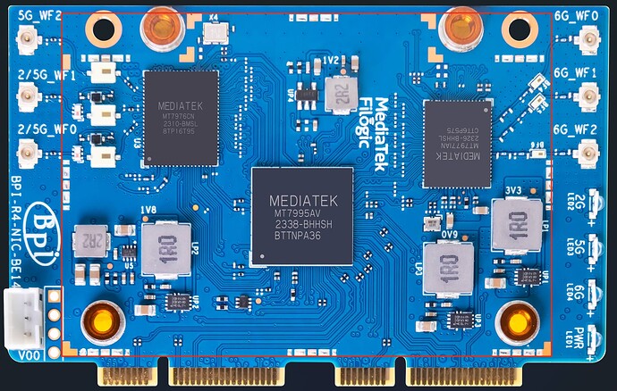
Thanks for sharing your noise figures. I wonder if they could be improved by putting an RF shield on the BE board. It already has a line of solder pads around the ICs for that purpose. Plus, it would be nice if someone with the knowledge of RF circuit design took a look at the schematics to check if the noise is related to things like insufficient output filtering on voltage converters, etc.
Here @simon mentions that the new WiFi 7 module models will use ePA (external power amplifier):
Thanks for sharing those tips. The stock firmware doesn’t report SNR and noise for clients, but I observed the same disproportional drop in transfer speed from the client to the router at distance. Turning off the 2.5 GHz radio didn’t help either. Even the proprietary driver likely isn’t perfect at this point to rule out a software issue, but I’m starting to suspect a hardware one.
It’d be nice if someone from the dev team took notice and shared the CAD for the RF shield so we could order one that would be a perfect fit. I’m sure they had it designed even though the shield didn’t make it to production. I’d like to try a makeshift shield made out of a piece of thin metal, but my BPI-R4 is buried inside its stock housing and already set up as a primary home router, which makes experimentation difficult.
@simon Would you spare a minute to chime in to point out the likely source of high noise on the BE14 and whether there’s something we could do to reduce it?
I could help, my BananaPi is still in “experimental” state - I’m more the software guy and don’t have that much experience in RF-tech, so perhaps some stupid questions:
- client/server noise level difference: Do we need to measure the noise level on the bpi r4 itself, as each device has his own noise on the receiver side? Because if I open a tool like NetSpot an my Mac, the noise is fine (in the -95 dBm region), but I assume, this is just the noise as measured on my client. The bpi r4 has its own noise level for its receiving end.
- noise level reported correctly?: Can we be sure the reported noise level on bpi r4 is “correct”? I assume, as you experience drops in bandwidth as you move farther away, this is a sign of problematic signal detection. So transfer from bpi r4 → client are still ok, and you only see drops client → bpi r4? I try to measure the behavior on mine.
- foil around module: Perhaps my most stupid question: should I try to shield the parts of the module DIY as an experiment - was thinking of placing some aluminium foil in a plastic bag (so foil is insulated and will not produce a short). And what parts should be covered - I guess it does not help to wrap the whole module. But it might change RF characteristics: foil+plastic might in fact act like a capacitor?
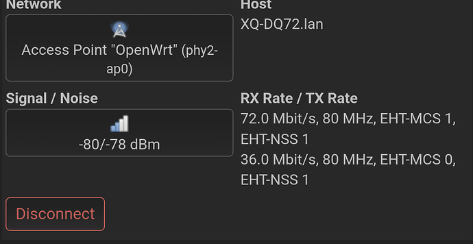
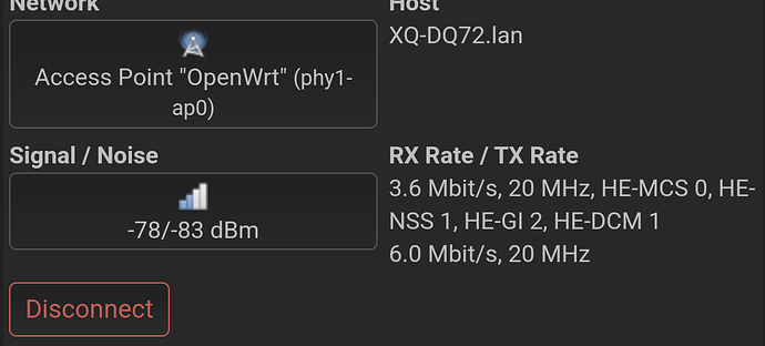
Edit: As a follow-up: I see the same behavior in drops of bandwidth as I move farther away from the bpi-r4 wifi: While the throughput (measured with iperf3 in reverse more) bpi-r4 → client only drops slightly, I see very large drops from client → bpi-r4. Additionally OpenWRT GUI reports a sharply dropping RX rate as I move farther away, while TX rate has much less drop, stayed almost the same.
Awesome! I’m glad you’re willing to help.
- Yes, you’ll have to look for the signal and noise levels displayed on the BPI-R4 for clients. Noise level is specific to the receiving device, the router in this case.
- I don’t know if it it’s possible for the router to be overestimating the noise, but the outcome is the same and we could still try to offset that by shielding. Low SNR makes the transmitter switch over to lower MCS Index, thus restricting the throughput.
- I suggest to first find the channel that would provide the lowest noise level and better throughput. In my case, switching from channel 36 to 132 on the 5 GHz band alone dropped the noise by ~10 dB and improved speed. Channel 100 was even better, but it’s not allowed in my country and some clients won’t even search for networks on that frequency if they have their geolocation turned on.
- The area is outlined by the unused solder pads for RF shielding, that’s pretty much the whole module.
 I’d simply form a tight (the tighter, the better) box-like cover over the BE14 board with well-insulated foil. It should then be connected to any ground point in the system to act as a shield, no meaningful capacitance added. The only issue would be cooling the three ICs, but they should be fine for quick noise measurement.
Edit. For better insulation I’d cover the foil in two layers of plastic tape rather than using a bag and put some tape on the mainboard around the Wi-Fi module to be extra safe. Foil could also serve to transfer heat from the wireless ICs if small cut-outs are made in the tape to put thermal pads between the ICs and the foil.
I guess I would also need to cover the back of the board (at least on pictures I also see those traces for omitted RF shielding).
Good catch. I’ve rarely seen backside shielding on PCBs, but those pads were put there for a reason.
Here you can see internal photos of several WiFi routers and ALL have RF shielding:
- ASUS RT-AX89X
- Acer Predator W6
- ASUS TUF-AX6000
- Ubiquiti UniFi 6 Plus
- GL.iNet GL-MT6000 (Flint 2)
- Linksys E8450 (aka. Belkin RT3200)
@sinovoip and @simon, why didn’t you put RF shielding on all the chips? This is the most basic of the basics. I don’t understand how you decided to save a few cents on something that is very important in a WiFi router and @dangowrt, as a developer and beta tester, why didn’t you inform them that this is important?.
Oh man I don’t wanna buy another WiFi card, they’re already expensive as it is
