BPI R4 WiFi range

I could help, my BananaPi is still in “experimental” state - I’m more the software guy and don’t have that much experience in RF-tech, so perhaps some stupid questions:

  • client/server noise level difference: Do we need to measure the noise level on the bpi r4 itself, as each device has his own noise on the receiver side? Because if I open a tool like NetSpot an my Mac, the noise is fine (in the -95 dBm region), but I assume, this is just the noise as measured on my client. The bpi r4 has its own noise level for its receiving end.
  • noise level reported correctly?: Can we be sure the reported noise level on bpi r4 is “correct”? I assume, as you experience drops in bandwidth as you move farther away, this is a sign of problematic signal detection. So transfer from bpi r4 → client are still ok, and you only see drops client → bpi r4? I try to measure the behavior on mine.
  • foil around module: Perhaps my most stupid question: should I try to shield the parts of the module DIY as an experiment - was thinking of placing some aluminium foil in a plastic bag (so foil is insulated and will not produce a short). And what parts should be covered - I guess it does not help to wrap the whole module. But it might change RF characteristics: foil+plastic might in fact act like a capacitor?

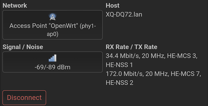
Edit: As a follow-up: I see the same behavior in drops of bandwidth as I move farther away from the bpi-r4 wifi: While the throughput (measured with iperf3 in reverse more) bpi-r4 → client only drops slightly, I see very large drops from client → bpi-r4. Additionally OpenWRT GUI reports a sharply dropping RX rate as I move farther away, while TX rate has much less drop, stayed almost the same.
2 Likes

Awesome! I’m glad you’re willing to help.

  • Yes, you’ll have to look for the signal and noise levels displayed on the BPI-R4 for clients. Noise level is specific to the receiving device, the router in this case.
  • I don’t know if it it’s possible for the router to be overestimating the noise, but the outcome is the same and we could still try to offset that by shielding. Low SNR makes the transmitter switch over to lower MCS Index, thus restricting the throughput.
  • I suggest to first find the channel that would provide the lowest noise level and better throughput. In my case, switching from channel 36 to 132 on the 5 GHz band alone dropped the noise by ~10 dB and improved speed. Channel 100 was even better, but it’s not allowed in my country and some clients won’t even search for networks on that frequency if they have their geolocation turned on.
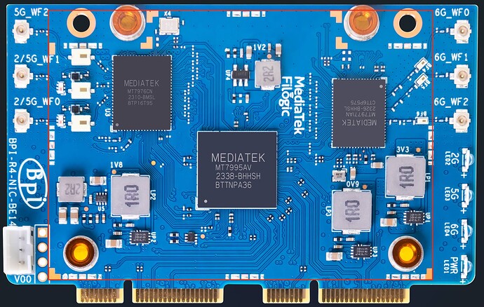
  • The area is outlined by the unused solder pads for RF shielding, that’s pretty much the whole module. :slight_smile: I’d simply form a tight (the tighter, the better) box-like cover over the BE14 board with well-insulated foil. It should then be connected to any ground point in the system to act as a shield, no meaningful capacitance added. The only issue would be cooling the three ICs, but they should be fine for quick noise measurement.

Edit. For better insulation I’d cover the foil in two layers of plastic tape rather than using a bag and put some tape on the mainboard around the Wi-Fi module to be extra safe. Foil could also serve to transfer heat from the wireless ICs if small cut-outs are made in the tape to put thermal pads between the ICs and the foil.

1 Like

I guess I would also need to cover the back of the board (at least on pictures I also see those traces for omitted RF shielding).

1 Like

Good catch. I’ve rarely seen backside shielding on PCBs, but those pads were put there for a reason.

1 Like

Here you can see internal photos of several WiFi routers and ALL have RF shielding:

@sinovoip and @simon, why didn’t you put RF shielding on all the chips? This is the most basic of the basics. I don’t understand how you decided to save a few cents on something that is very important in a WiFi router and @dangowrt, as a developer and beta tester, why didn’t you inform them that this is important?.

1 Like

Oh man I don’t wanna buy another WiFi card, they’re already expensive as it is

1 Like

I have an idea for this one, maybe we can find a shield that fits the board and put tape on and put thermal pads between shields and chips and one big thermal pad outside between shield and case

1 Like

A potential problem is: the shield can‘t be rectangular, as it would then cover the screw holes and you can‘t screw it on the mainboard anymore. Perhaps we could drill a hole into the shield and later cover it with some spare metal…

In the meantime I bought some copper foil from my local hardware store - but they only had 0.5 mm thick ones, that‘s not that easy to bend…

1 Like

Hmm what thickness would you recommend, also let us know if it makes a difference

From my kitchen and the router is in my living room

1 Like

Did you make any change to get -89dBm noise level? I’m getting far worse (-75dBm)

1 Like

I’m not using BPI antenna, I’m using the Taoglas antennas

1 Like

Channel selection can also make huge difference.

1 Like

BTW, if you look on any bpi products, none seem to have any RF shielding - not even the OpenWrt One or bpi-r3 (although they seem to have a heatsink at a relatively good place and will probably cover most chips) - but would be interesting to know if bpi-r3 or OpenWrt One might have similar noise levels?

1 Like

It would be great if someone knowledgeable could experiment with rf-shielding. I think the range is decent but it’s the noise that seems to be killing SNR.

1 Like

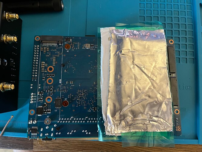
So, I did some experimentation. To make an RF shield I used a piece of aluminum window flashing which has a thick adhesive layer that made it easy to shape around the Wi-Fi board (front and back side) leaving only small gaps for pigtails to pass through. Needless to say, I had the PCBs throughly insulated with high-density sticky tape. The shield was then connected by an alligator lead to the barrel of one of the SMA antenna sockets to provide ground.

Here’s the results. 5 GHz band, channel 132, 80 MHz. The client was a 2021 MacBook Pro, which had the most problems with the BPI-R4 out of all my devices. Distance of ~5 meters to the router, line of sight partially obscured by a concrete wall.

Baseline (stock BPI-R4 housing, no shielding): -65/-71 dB, ~100 Mbps throughput

RF shield added, the board is out of the housing: -65/-80 dB, didn’t check throughput

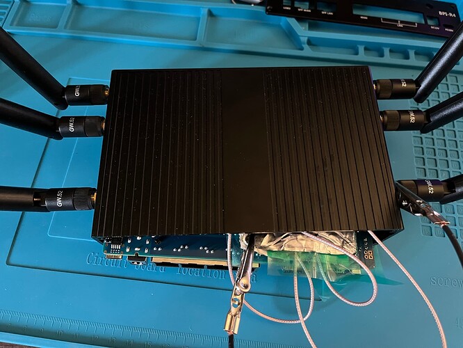
RF shield added, the board partially inserted into the housing (see picture): -65/-85 dB, 300+ Mbps throughput

I have to admit the old Archer C7 still has vastly better noise level at -107 dB. But my ghetto shield was far from perfect as shown by the difference the metal housing made, which provides some shielding of its own from external RF sources. As a general rule, it’s OK to have holes in shielding, but long slot-shaped gaps will allow the radio waves to leak through, that’s why the shield has to sit tight against the PCB. Mine clearly didn’t.

Still, there we have it. The BE14 was indeed hamstrung by the missing RF shield. I took measurements of the board and will come up later with dimensions and mounting system for a proper implementation.

P.S. This was an experiment with the sample size of 1. More people are welcome to try what I did and verify my findings. Just, for the love of God, do your best not to fry the board by short-circuiting something with metal foil.

3 Likes

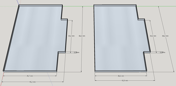
Here’s the dimensions of RF shields for the front and back side of the board (yes, they are slightly different) assuming thickness of 0.2 mm, which is common and sufficient. 2 mm of inside height will be enough to clear the tallest components on the front side.

The shields can be soldered directly to the pads on the PCB. Better yet to use shield can clips. Ones that fit the pad layout exactly are S0961-46R from Harwin (see datasheet). Each side will take 8 of those.

As for the material, copper would be the easiest to work with and easy to buy in 0.2 mm sheets from an arts and crafts store. I’d like a factory-made solution, but even though individual cans are cheap to manufacture, ordering them to custom spec would incur an upfront cost of hundreds to thousands of dollars for tooling.

Edit. Shield height for the back side needs further cheks to make sure it won’t touch any components on the main board.

2 Likes

I measured 1.8 mm height of the largest component on the front side of the pcb - have not measured the back.

2 Likes

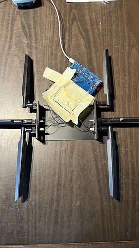
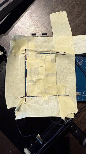
I had less luck with my method, I tried a very simplistic form: I only covered the front side, as seen in picture:

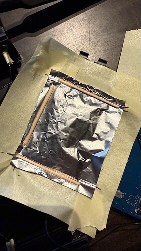
I then placed some aluminium foil on top:

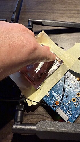
and then applied some pressure, so it will connect the grounding points on the pcb:

But my noise level approximately stayed the same: it was -84 dBm without foil and stayed at -83 dBm with foil. So as you wrote: even a tiny little gap or the missing shielding on the backside and it will not work - I try to add some shielding on the back and report back…

I also ordered some thinner copper foil (0.1 mm and 0.2 mm) together with some kapton tape (for inside isolation with cutout for the 3 chips and will apply some thermal pads between chips and copper) and will solder it on the board when it arrives.

→ EDIT: I now just saw your clips - that would be even better, so I don’t need to solder the copper on the board directly!

I also asked in the OpenWrt One thread for noise levels, as the heatsink also has quite some gap between board and sink.

2 Likes

I also didn’t get any sizable improvement in noise dB until I wrapped the whole module in foil. Connection to ground was probably the issue in your case too. As for the cooling, although I didn’t put any heatsinks or thermal pads under the foil, the Phy ICs were barely touching 70 °C after 5 minutes and there’s no need to run them like this any longer than that.

1 Like