Thanks for pointing that out. I will just order a 5v, PWM fan and use the FAN2(3Pin) connector. However, I have already butchered the case to fit a 50x50mm fan and I am unable to find a 50x50mm, 5v Pwm fan! I have ordered a 40x40mm, 5v, PWM fan. Now i need to figure out how to cover up the butchered case hole that will be slightly bigger for the new fan. ![]()
So I can safely use ground pin of FAN1(2pin) Jst connector as a PWM signal lead and plug in a 12V-PWM fan into 12v and Grnd elsewhere on the board without having to de-solder and solder R317 and R318?
you could use pwm-pin (gnd) and the 12v pin from the connector near the power jack together…but imho you always need a pwm capable fan…tried with normal 5v fan on 2pin-connector and it does not work. maybe i need to add capacitor in parallel to hold voltage a bit (not bring rectangular signal to the fan)
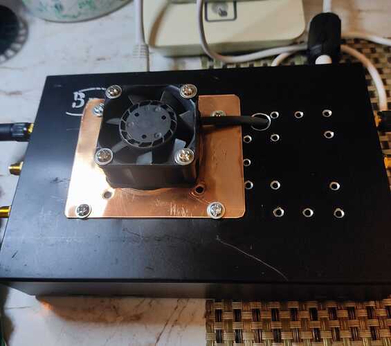
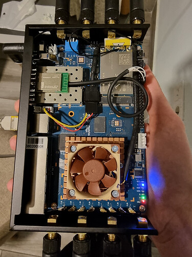
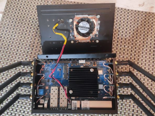
Update: I ordered a 5v PWM fan, modified the case and fan connector, plugged it in and it only spinned for few seconds on boot. Then read through other posts in this thread and figured out the trip points and used echo 45000 > /sys/class/thermal/thermal_zone0/trip_point_3_temp command over SSH. The fan came alive and is working without a glitch, it won’t led the temperature cross 45 degrees Centigrade. Only problem is that this fan is a bit loud. Now I have to search for a quiet 5v (40x40mm) pwm fan. Here is a picture of My BPi-R3 Fan Mod.
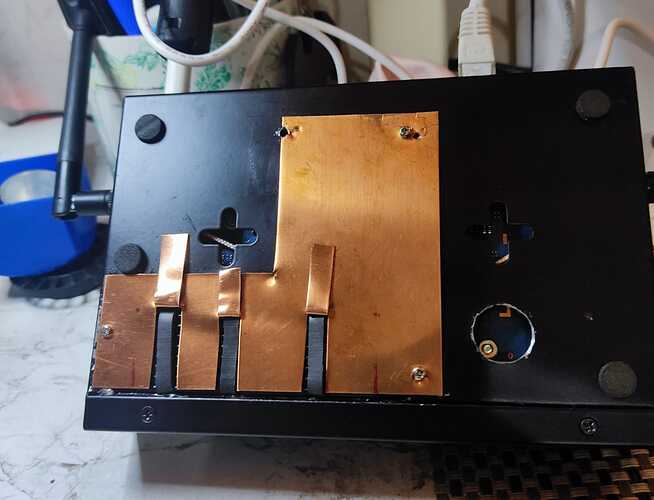
and here is picture of bottom mod, now I can access the SSD, Heat Sink Screws and R317/R318 if I ever wanted to switch Fan voltage from 5v to 12v. Now I am only 3 screws away from changing the SSD and don’t have to worry about removing the antennas and the PCB to to do so.
WTF is that ?! I have the official rad/fan, my fan is configured to start @50°c, it never started runing this summer, I’ve never reached this temperature.
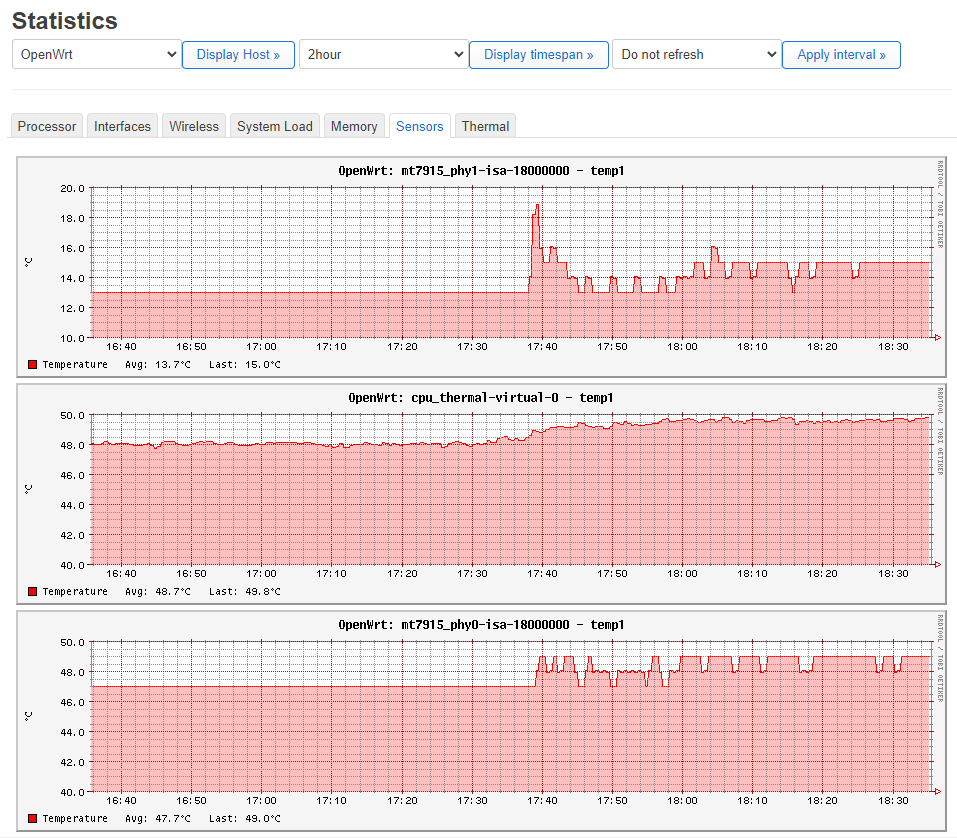
This is actualy my temps in a 20°c room.
I’ve never had to make extra holes in my case. In fact, just the radiator is enough, the fan is really if you live in the middle of the Sahara. ![]()
Haha, I am not that good with cutting metal, I badly butchered the case in the process and then had to use .5 mm copper plate to cover up the mess. ![]() For me at room temperature of 25°C my BPi-R3 calls for the fan, all guns blazing, in about 15 minutes and from then on the fan keeps turning on and off in little spurts of few seconds to maintain the temperature of 45°C, the fan gets to pause for longer if I set the trip point at 51°. I am not sure why yours is so cool, mine gets hot rather fast. Thats ok though, since I like my stuff hot
For me at room temperature of 25°C my BPi-R3 calls for the fan, all guns blazing, in about 15 minutes and from then on the fan keeps turning on and off in little spurts of few seconds to maintain the temperature of 45°C, the fan gets to pause for longer if I set the trip point at 51°. I am not sure why yours is so cool, mine gets hot rather fast. Thats ok though, since I like my stuff hot ![]()
did you add a radiator on the chips ?
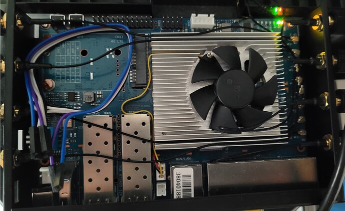
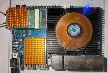
This is my BPI-R3
in my case just the radiator would be enough, as the fan never start…
yup, 60 x 60 x 10mm Black Anodised Aluminum Heatsink Cooler Radiator, that covers the main chips except for WiFi chips which have smaller Raspberry pi radiators of their own. eMMc chip is partially covered by the 60mm sink.
How can you lower the temperature from 60º to 45º for example? I mean, what’s the file to change in OpenWRT for a pwm fan?
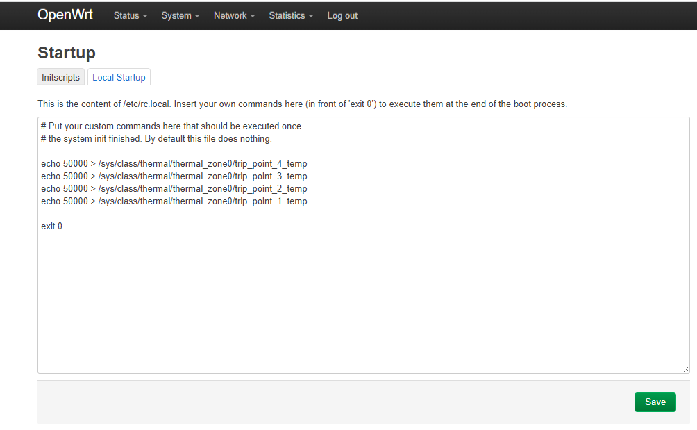
echo 50000 > /sys/class/thermal/thermal_zone0/trip_point_4_temp
echo 50000 > /sys/class/thermal/thermal_zone0/trip_point_3_temp
echo 50000 > /sys/class/thermal/thermal_zone0/trip_point_2_temp
echo 50000 > /sys/class/thermal/thermal_zone0/trip_point_1_temp
This will activate the fan at 50°c, for 45°c change the value to 45000
as mentioned in the screenshot, the file is : /etc/rc.local
I also tested the “new” echos for changing trip_point values.
My setup is a 55mm fan (PLD06010B12HH 12V 0.40A). The fan is capable of handling 5V and 12V. With 5V it runs slower. But I resoldered the 0Ω resistor on the bottom from R317 to R318. So it runs with 12V.
As the picture shows, i use the “normal” 3 pin port with PWM for running the fan.
My R3 runs the last stable openWRT firmware:
My results:
Yes, it is possible to set different values which effected the fan speed. I “read” how much work this was! ![]()
![]()
![]() I really like reading and working on the fan topic.
I really like reading and working on the fan topic.
But for me nothing changed. The fan runs the whole time and I can NOT turn the fan off ![]() . It is quiet and on the border to be hearable. With one or two meter distance, I would accept this at night (trip_point_1 & trip_point_4)!
. It is quiet and on the border to be hearable. With one or two meter distance, I would accept this at night (trip_point_1 & trip_point_4)!
During the useage of trip_point_2 & trip_point_3 the fan is too loud. And for the temperature I did not need it. For case usage, I would prefer to do much more holes in the case. Only the last choice would be turn on trip_point_3.
What I need would be manipulating the fan speed of the trip_points or that the fan turns off and on (lowest level <trip_point_1 & trip_point_4>).
If the future brings no advanced possibilities, I will may go back to 5V (fan runs lower) or try to use a resistor instead of 0 Ω resistor (R317 to R318) to lower the speed.
why did you use echo 05000 instead of 50000 ?? it means the fan will start at 5°C ![]()
Hello Rooot,
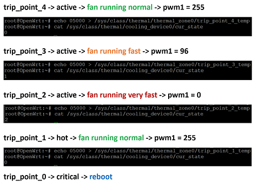
“my results” only show the summary of my attempts. The question was how to find out what every trip_point causes. I don’t want spend more time than i have to on this topic. So I had to found a temperature that activated only one trip_point per try.
The temperature of my CPU is 23°C.
Example for trip_point_4:
I’m hoping you understand it now. The other trip points are at 99,999°C and will not be activated. I could also take 10000 (10°C) or 20000 (20°C) → the purpose was to activete trip_point_4.
For presenting the results I have done the followed:
first:
second:
Why are you using the same temperature for trip_point_1-4:
My tests showed that the fan runs faster during the active trip_point_2 and lower at trip_point_3 (lowest was 1&4). I also find out, in case if you use the same temperature trip_point_2 will be activated!!!
Why not doing this?:
If the temperature is getting faster the fan will run faster!
Hi.
Do you have thermal pads over each chip under the official fan?
Thanks in advance.
I recently bought this self-adhesive thermal pad in combination with Skived Heat Sink which I still got to cut to dimensions. Worth to note that I 3D printed a case where all three parts, especially when it comes to ensuring the heat sink doesn’t fall off causing damage to the board, must be adjusted accordingly.
The offical fan should be delieverd with thermal pads. I do not have one, but looked on aliexpress:
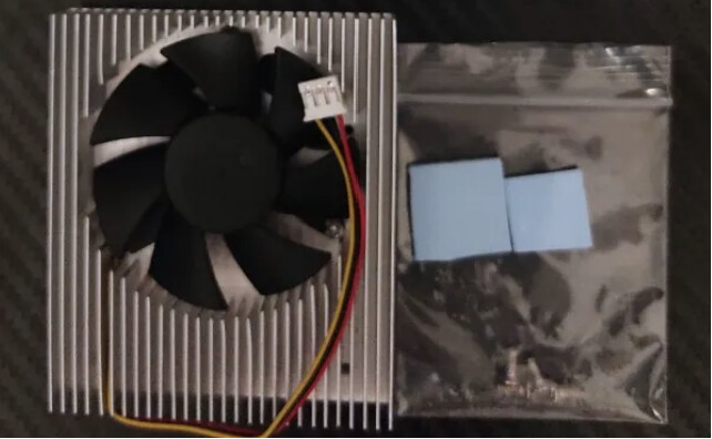
Please use thermal pads ![]()
not on the wifi chips, there are only 2 pads in the kit…anyway my temp is always below 50°c and my fan never start…or it starts but I never hear it even though it’s 1 meter away from my head
as you can see below, even with no thermal pad, and no contact between the wifi chips and the radiator, the temp never reach 50°c, My office is actually at 20°c
Ok.
I have put thermal pads over each chip under the official fan.
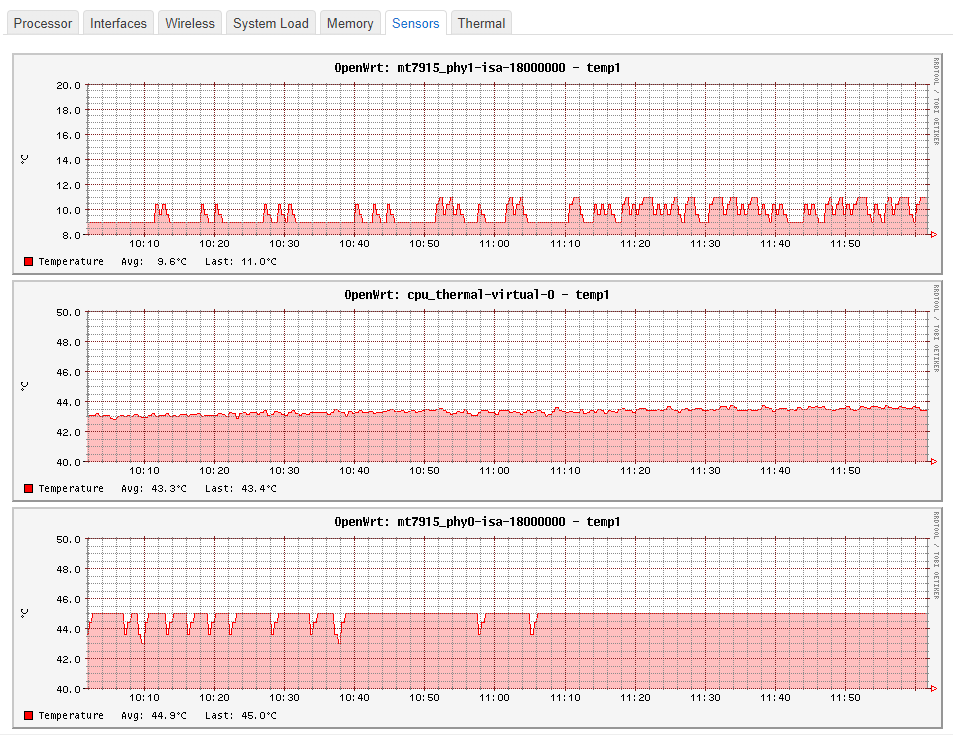
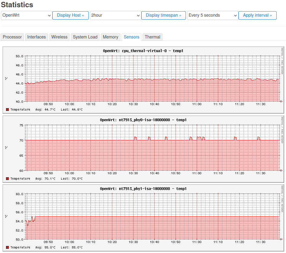
Cpu is running with a stable 44/45 º C.
Mt7915_phy0 shows a wrong temperature, but I can live with it ![]()
Thanks for those commands! The first only workable/easy solution I found here and elsewhere… those were my temps before running them:
root@OpenWrt:~# sensors
mt7915_phy0-isa-18000000
Adapter: ISA adapter
temp1:        +53.0°C  (high = +120.0°C, crit = +110.0°C)

cpu_thermal-virtual-0
Adapter: Virtual device
temp1:        +54.4°C  (crit = +125.0°C)

mt7915_phy1-isa-18000000
Adapter: ISA adapter
temp1:        +86.0°C  (high = +120.0°C, crit = +110.0°C)
And after letting the system go for a little while with no load nor connections (just starting to provision my BPI-R3 now):
root@OpenWrt:~# sensors
mt7915_phy0-isa-18000000
Adapter: ISA adapter
temp1:        +45.0°C  (high = +120.0°C, crit = +110.0°C)

cpu_thermal-virtual-0
Adapter: Virtual device
temp1:        +44.6°C  (crit = +125.0°C)

mt7915_phy1-isa-18000000
Adapter: ISA adapter
temp1:        +78.0°C  (high = +120.0°C, crit = +110.0°C)
I think it’s a shame that more conservative defaults are not applied since the case was fairly warm to the touch and could have damaged my system eventually… in other words: out of the box configs should not self-destruct the router ![]()
