First I need to confirm that the PWM problem is not hardware related. Any idea how I can check this?
you can build openwrt with kernel 6.1 from daniels tree which should be right now (5.15 seems to not working with the clock i upstreamed).
Do you have an oscilloscope or voltmeter?
Please give me the instructions how to check it. I will have access to oscilloscope and voltmeter tomorrow.
With the ground probe touch the sfp cage or any other gnd pin, and with the other one the pwm pin, which is the one closer to the sfp/eth ports side of the board.
Then type
echo 2 > /sys/class/thermal/cooling_device0/cur_state
And you should see pwm signals for few seconds, maybe ask someone to help you
Please do not shorten pins…best way is to use a matching connector with cables for testing it. You can also measure voltage with multimeter between gnd (middle pin) and the pwm pin. If pwm is off you will measure 3v3 as pwm high brings gnd to the pin (inverted signal)
1 Like
It’s riskier trying to use the middle pin for gnd. The sfp cage is very convenient
1 Like
Thank you! Voltmeter or oscilloscope? A friend of mine will help me.
With scope you will see the pwm signal, with voltmeter you should see a temporary voltage increase
If your friend or you can handle oscilloscope correctly it will be better choice as you will see the signal shape. Multimeter is easier but you see only voltage change when pwm goes through the states
Do you know which trip point is activated when? I have 0 , 1 , 2 , 3 , and 4 So setting the trip point 1 to 32000 didn’t do anything, so I set
echo 32000 > /sys/class/thermal/thermal_zone0/trip_point_4_temp
echo 32000 > /sys/class/thermal/thermal_zone0/trip_point_3_temp
echo 32000 > /sys/class/thermal/thermal_zone0/trip_point_2_temp
echo 32000 > /sys/class/thermal/thermal_zone0/trip_point_1_temp
and now the fan actually spins! YEAH! It is keeping it much cooler, as it was very hot, and hot to touch before. So thank you for pointing me to the trip points but I am not sure what the levels are and how the different trip points affect the fan speed at each point?
1 Like
what 32000 means ? is it the temp in °c * 1000 ? so if i set 40000 the fan will start @40°c
Yes,the temp-value of trippoints is in millicelsius
Mainline has current problems merging dts changes,but i thought daniel has merged my latest version into openwrt where the lowest trippoint is active. I guess you need to update temp from second trip point as only active trips can trigger fan
1 Like
My room is at 22°C, my BPI case is closed, and the temp reported is 46°c. I don’t think that’s really hot… Anyway i tested the commands above @32000 and after that i checked @44000

i think i will set the value to 50000, that’s way enough for me.
tested with official heatsink (with integrated fan), fan runs at level 1 & 2 as it should, so imho current version with fix i’ve sent is correct. also tried using a non-pwm fan (2pin 5v) on the the pwm-pin (+gnd), but this does nothing.
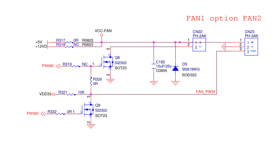
Anyone have any idea on how many volts the 2 PIN fan connector on BPi-R3 should be giving? I was assuming that by default both FAN1 (2pin) and FAN2 (3Pin) ports should be at 5v by default. But a 5v fan does not power up when plugged into FAN1(2Pin) port. It works just fine when using 2 pins of FAN2(3Pin) port. Using a multi-meter I checked both FAN1(2pin) and FAN2(3Pin) and FAN1(2pin) is giving 2.5v instead of 5v. FAN2 (3Pin) is giving 5v as expected. Can anyone else confirm if the FAN1(2Pin) port on their board is giving 2.5v or is there a defect in my board?
Voltage should be on both 5v,but because the pwm-pin is only partly at gnd the measured voltage is lower…,you can measure the voltage with another gnd and then it should be 5v
You are right, FAN1(2PIN) JST Port on the board does show 5v if I do not use the Ground pin of the JST port when testing using a multi-meter.
However, to me that does not make sense, what is the use of this FAN1(2PIN) Port? Since, It can not power a 2Pin-NON-PWM fan, what is the intended use?
Does this mean that FAN1(2PIn)-Jst port also has PWM control capability if ground is used from elsewhere on the board?
Currently, since this port is not able to power the 5v fan being used, I am using 2 pins from FAN2(3PIN) Jst port to power a 2Pin-NON-PWM 5v fan. It would have been nice to be able to use 2Pin port for 2 Pin 5v fan!
Putting the mosfet in the ground connection has 1 advantage.
The pwm pin can be used together with another supply pin, for example 12v.