You could buy those clips mentioned in this thread somewhere and not have to solder the shield directly to the board
That’s a solid plan, but soldering directly to the board will make it harder, not easier. You’ll already have a large ground plane to bring up to temperature, for which I recommend using a bottom heater (there are cheap ones on AliExpress). Now add a comparatively massive shield can to it, and you risk either getting cold solder joints or damaging the board by local overheating. Not to mention burying thermal pads under the heat shielding forever, which might also get damaged by the heat. The clips, on the other hand, can be easily soldered with paste and hot air (still I’d use a bottom heater).
true, but I don’t mind soldering them down… Don’t think I would need to open that thing again ![]()
ok, have not considered those downsides! I will reconsider!
I will order some clips on Ali then ![]() thanks!
thanks!
1 Like
Wait with the paste are you talking about thermal paste or that liquid solder paste
Solder paste. It’ll make the clips self-align to the pads.
Ah interesting, I should probably buy some soon
Do you have a specific bottom plate heater that you recommend
I have a 500 W soldering plate instead of a proper preheater (like this one), and it is dirt cheap. To control the temperature I simply move the board closer or farther away from the plate and check with an IR thermometer until I get it to ~100-150 °C. Worked well so far for replacing SMD capacitors on graphics cards.
1 Like
I tested my measurements with 3D-printed mockups, and I’m finally confident to say they’re good to go. Here’s the DXF drawings and STEP models (bend radius accounted for) of the shield cans to keep everything in one place.
shield_can_top.step (252.4 KB) shield_can_bottom.step (473.6 KB) shield.can.bottom.dxf (11.0 KB) shield.can.top.dxf (13.5 KB)
1 Like
Oh nice, waiting for you to do it with copper and see if it has any effect
1 Like
Cool - BTW why do you have made holes in the shields?
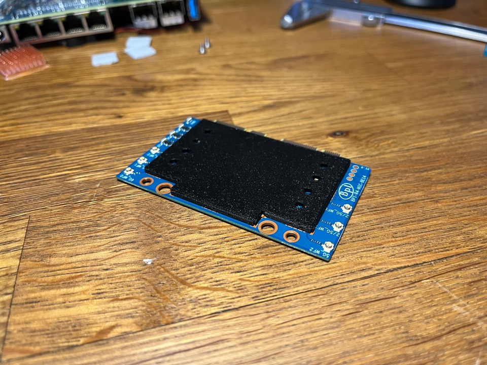
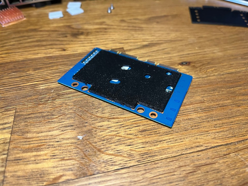
The eight holes in the top-side can are there to provide a semblance of airflow to the SMD components on the board beside the large ICs, which are going to be covered by thermal pads. It’s quite common in RF shields to make small holes like that, and they won’t hurt the shielding effectiveness. The holes on the bottom part are necessary to clear the tall SMDs on the main board, otherwise there just isn’t enough clearance between the PCBs.
Question about a shielding idea:
Has anyone ever tried to cover a thin metal plate with heat conducting pads on the inside and outside and use this as a shield?
Are such thin pads also available for a shielding between the BE1400 board towards the BPI-R4 board?
This may be a combined heat dispenser and shielding solution.
Hello, I am an electrical engineer. Thank you everyone for your time looking into the RX noise so far. I’m suspicious that the 3V3 regulator UP3 (MP8759) is one of the major sources. Possibly also U9, U14, U15 (MP2338). These regulators are all close to the BE14 when installed, albeit on the topside of the R4 PCB. Additionally, Betonmischer mentioning that populating the SFP cages improving the noise floor would make sense if the additional loading is stopping U9 from pulse skipping.
1 Like
But the problem with SFP cages is that the cage isn’t even connected to ground at all, not sure how it improves the signal
Since I don’t have a R4 on hand to test, can someone tell me if the two posts used for screwing down the BE14 are connected to the ground plane? I assume they are and was wondering if using tape and plastic screws so that the R4 ground plane and BE14 ground plane don’t connect through them makes any difference, better or worse.
I’d also be curious to know if a copper foil shield, taped to the bottom of the R4 PCB and soldered to the R4 ground plane specifically, makes any difference.
Hmm I would normally check but the R4 is being used as a main router for me
Yes exactly, I am saying that the SFP modules drawing power from the regulator is why it might be quieting the noise down. Nothing to do with the SFP cages being grounded or acting as shields themselves
Tbh tho I don’t think the SFP makes a difference, I got 2 filled slots and I still get -85dbm when 6ghz is at 80mhz width and -81dbm when at 160mhz probably even less at 320mhz