I also wondered whether the noise is, at least partially, related to poor filtering on power input. It’d be worth poking the 12V line on the BPI-R4 with an oscilloscope to look for excessive ripple. Looking at the schematic, it doesn’t even have any inductors on the output.
Yeah that is probably contributing to it
On the other hand I used a USB power bank as input source for my noise tests, that should not have any AC ripples (but of course might have other step-up/down converter noise)
I want to share my experience with the Banana Pi R4 router to warn other users about a significant issue with its Wi-Fi emission power.
I recently purchased a BPI-R4 hoping to improve Wi-Fi coverage in my two-story home. Previously, I had a NetGear R7350 that perfectly covered my entire house with its standard antennas. However, the BPI-R4, despite promising specifications, fails to provide similar coverage.
Initially, I tried to improve the signal by replacing the original antennas, but I contacted the vendor for recommendations. Their response was as follows:
- Emission Power Issue: The vendor informed me that the problem is not with the antennas, but with the router’s BE14 chip. This chip uses a built-in power amplifier ¶ that is not powerful enough and struggles to penetrate walls.
- BE14 Chip Limitations: They explained that even with an external power amplifier (ePA), performance in buildings with concrete ceilings would be poor.
- No Viable Solution: The vendor confirmed that there is no solution to this problem, as the limitation is in the BE14 chip’s hardware. Additionally, there are currently no other compatible Wi-Fi 7 modules.
- Vendor replies:
- “This is not a problem with the antenna. It is mainly because the BE14 uses a built-in PA, which is not very powerful and does not penetrate walls very well. If you live in a building with a concrete ceiling, the effect will not be very good even if you use ePA.”
- “The reason is that the wall penetration effect is not very good, there is no way to fix it. There is no other wifi7 module at present”
In summary, if you need a router with good coverage and signal penetration, especially in multi-story homes or with concrete walls, I do not recommend the Banana Pi R4. The power limitation of the BE14 chip makes it unsuitable for these situations.
I hope this information is helpful to other users considering purchasing this router.
Best regards,
1 Like
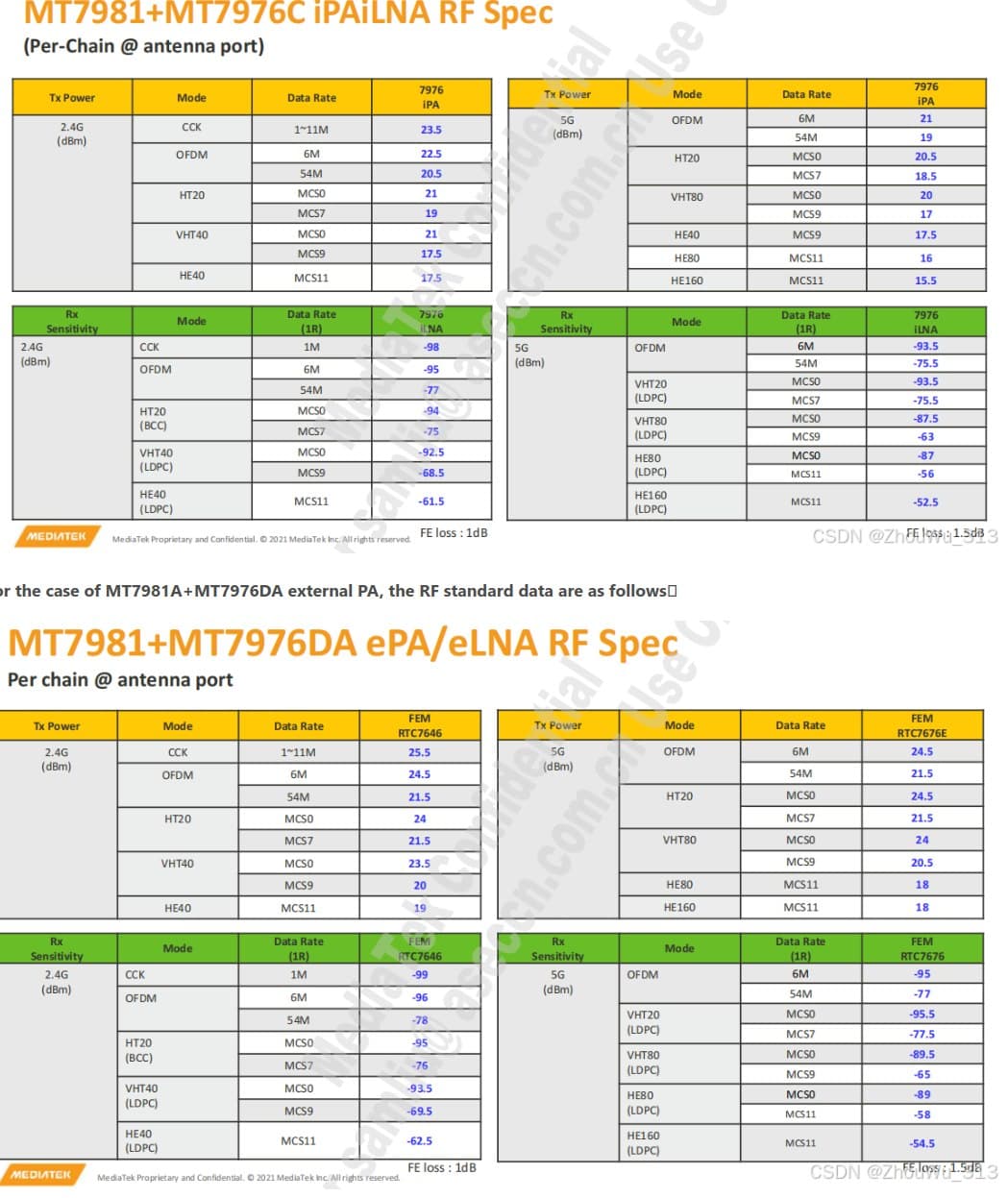
This explanation sounds strange - as BE14 does indeed send at 23/27 dBm (depending on country - as allowed by law). Only “a few” (I don’t know the percentage) BE14 boards have some power issues and limit tx power to 7 dBm - there is some workaround available as discussed here: wifi txpower value is very low · Issue #17489 · openwrt/openwrt · GitHub
The main problem seems to be the noise level on the receiving side. Most router have a sensitivity of around -90 dBm, while here we usually get something like -78 dBm on an BPI R4. So it can send strong enough, but has problems receiving a signal, so at the end it does not work great. But it does not seem to be a “power amplifier” problem…
mt7976CN has enough power for mobile clients even without external PA/LNA
I have no problems with dirty cheap (20$) mt7981+mt7976c iPA/iLNA routers with separated antennas for 2G and 5G.
Thanks for your answer, In my personal experience, had these issues with dBm tx power with some images later newer versions broke, then was solved again, etc. Currently SNAPSHOT r28958-d136c24f7c allows me to set at 20 dBm maximum, which on paper doesn’t sound bad but if I go to the second floor or to the garden I couldn’t connect to the router. If I set my old NetGear R7350 I have full power and good coverage in the same locations
You can connect but your router is struggling to receive, it’s suffering from emi
Hello fbarcelo,
as often discussed, these Banana Pi boards are development boards.
“I recently purchased a BPI-R4 hoping to improve Wi-Fi coverage in my two-story home.”
→ You are looking at this router board from an end-consumer perspective. You should not do this!
I’m not a programmer, but when I look at the board, the first thing I see is the missing shields:
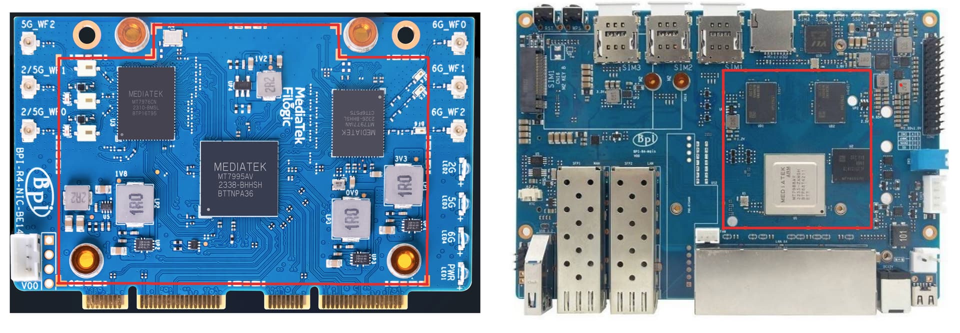
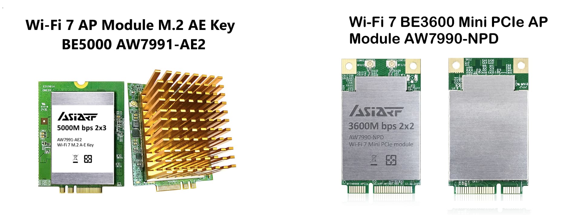
These are the Mediatek Wifi 7 Modules from Asia RF: → shields on both sides
The BPI-R3’s Wi-Fi range is also poor and it also has no shields. But like the R4, there are holes for the shield… I can confirm that changing the antenna will not solve the problem!
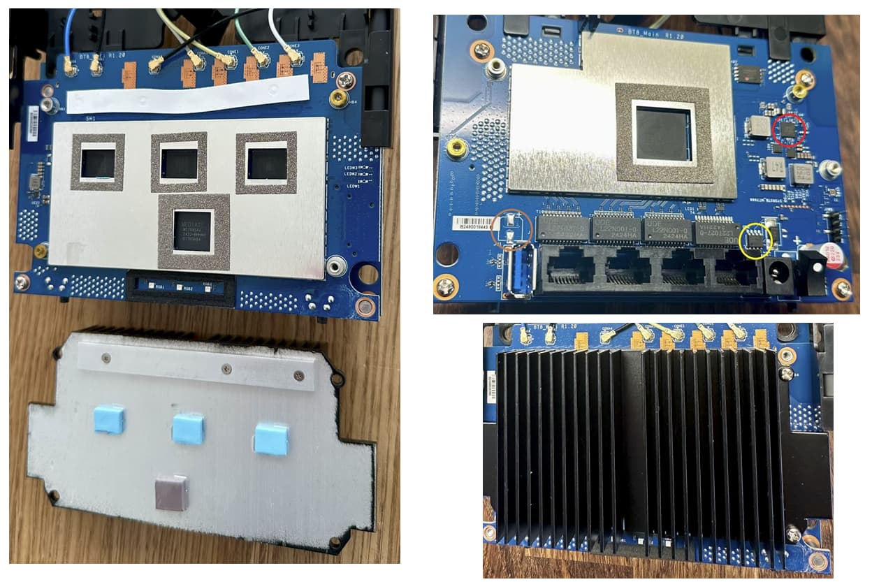
If you are interested in a Mediatek MT7988 there is the Asus ZenWiFi BT8 Tri-band Wifi7:
This is a good shielding:
Sorry that I have to tell you this ![]() !
It looks to me that Banana Pi focuses on supplying boards for software development.
!
It looks to me that Banana Pi focuses on supplying boards for software development.
If the Wi-Fi range limitations are unexpectedly caused by design decisions from Banana Pi, this will be a bad day for us all.
CPU wont need a shield it doesn’t pose that much of a problem it’s the WiFi card on this one, can definitely buy the clips to solder to the WiFi card, all we need is the DXF file of the WiFi card from BPI to make the shield as stated by @Betonmischer it should solve the problem
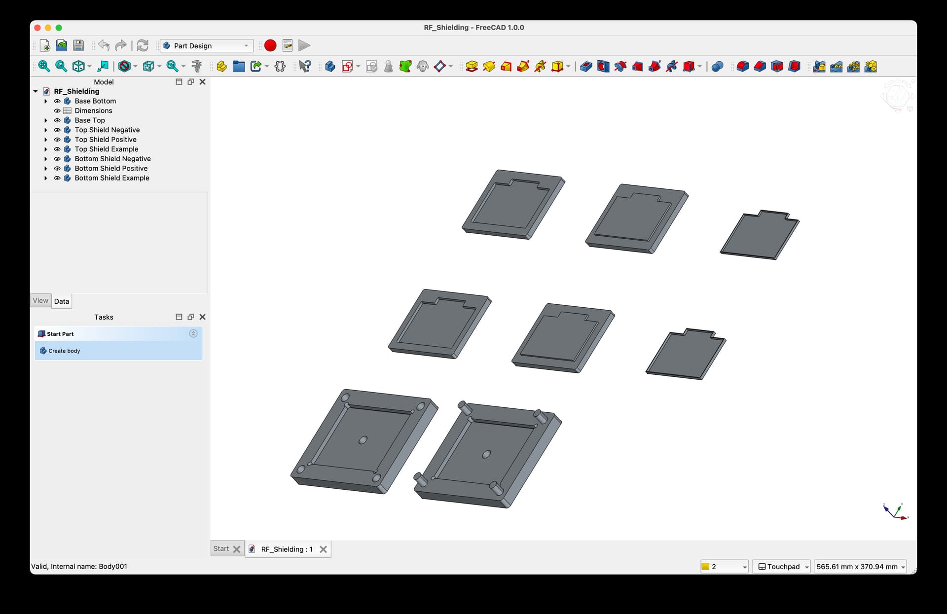
If you’re ready to do some prototyping, try those. I made them in Fusion to my best measurements for 0.2 mm sheet metal. After I beefed the thickness up to 0.4 mm, I was able to 3D-print them for validation, but there wasn’t enough free time yet to tear apart my BPI-R4 once again. The general plan is to outsource laser cutting, then press the shield cans into shape using a set of dies 3D-printed out of a stiff material (PLA or, better yet, PLA-CF).
shield.can.bottom.dxf (11.0 KB) shield.can.top.dxf (13.5 KB)
Edit. Both parts are meant to be bent towards the viewer, as seen after importing DXF.
2 Likes
The question is tho are those pads actually connected to anything or were they disconnected too
Thanks for your response. You’re right. With my previous experience building NAS, media centers, game consoles, and some home automation devices using various SBCs (mostly Raspberry and Orange Pi), I mistakenly assumed the board would be fully functional at the hardware level. I thought that, since it was a development board, I would at most have to deal with software/driver issues, which I did and partially resolved. But I didn’t realize the problems could also be in the hardware/design layer.
You learn from your mistakes.
Looking at the BE14 pictures, the solder pads lie on a ground plane, which is used by some SMD components.
Ah ok, if we could get the 3d model of the die I can check how much it’d cost
I’ll make one to match the DXF after I validate the dimensions with my 3d-printed drafts.
Although, If you meant ordering custom shield cans to be machine-pressed as intended, that’s thousands of dollars for the tooling.
Yeah I’d probably have the mold printed by jlc3d and shape the metal myself
This is true, a proper shielding is used in most routers. Interestingly all BananaPIs have no shielding at all - not even the OpenWrt One ![]()
I had no time yet, but I still plan to do some shielding. My plan is:
- I bought some copper foil 0.2 mm (and also 0.1 mm) thick
- Some Kapton tape which will be placed on the foil (for electrical shielding, so no shorts with the board)
- 3D print some “moldings” and then press the foil (I think “deep drawing” is the technical term)
- I tried with some simple shapes and it seems to work: the thickness of the shield is only 2 mm anyways.
- cut off the excess - if bent, I will press them using this mold again

- I will then solder them directly on the board…
So far I designed some molds using FreeCAD, but still need to print them… I used @Betonmischer measurements and they seem to be accurate so far.
The big thingies on the bottom are some “mounts” for the molds (so I can press them using a bench vise and everything stays aligned), not sure if I need them… the things on the right are “dummy” shields which I printed to verify the size match.