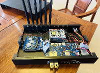
your 3D case is currently in the process of being implemented. Once everything is ready I’ll see if that’s enough. Or will a screen be needed) Although it turned out that my problem with BE14 is a bad revision with bad EEPROM firmware, due to which normal power cannot be achieved without additional patches.
Better to design model of this tool ВЧ экраны своими руками / Хабр It allows to make any rf emi sheelds (in range) witout usage of custom forms.
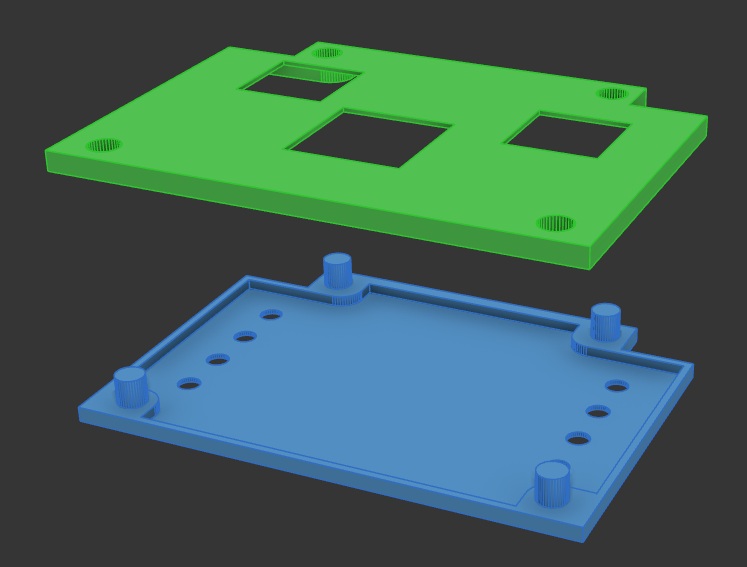
Did anyone check if the noise is reduced, when using the extension of this case:
Is that even out yet?
Donnow, if not, maybe @sinovoip looked at this? I would think that much high noise would be a trivial issue…
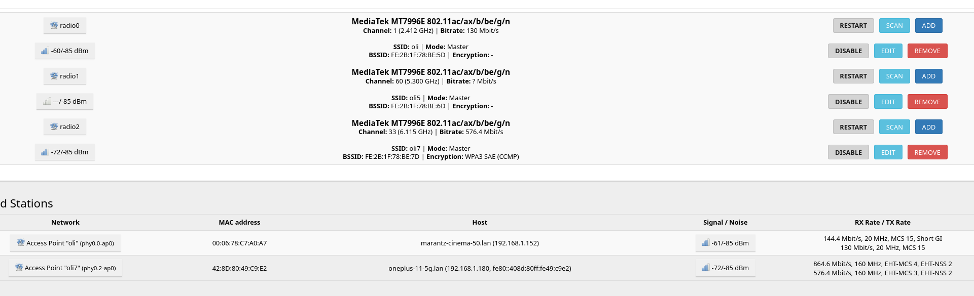
i replaced the antennas now with different ones. wondering if the new values are ok? the board is now without case and the antennas lay on the ground. when i find some time, i might assemble everything together, this evening or tomorrow… i guess -85 for noise is ok, right?
Yeah are you on 160mhz for 6ghz
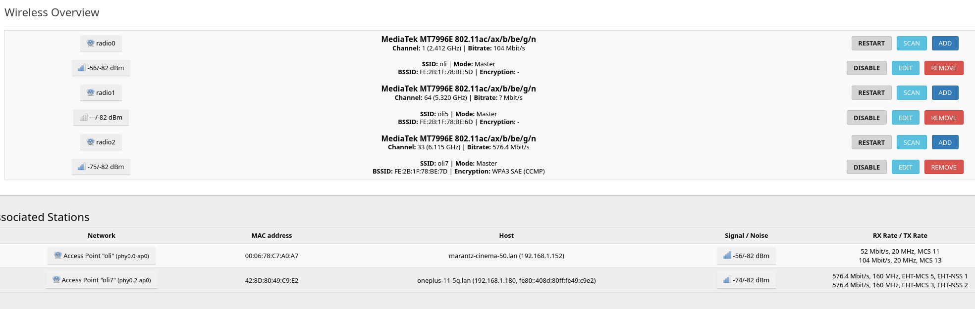
Yeah seems fine, I would do that power save things on the PCIE and it should go to -84~
Interesting would be if the wifi range is good for you now. But of course 5/6ghz is not working so far like 2.4 GHz because higher frequencies are more blocked by walls,furniture,…
i have nothing that blocks, except when i am in my room where the workstation is, but there i have lan. i tested now with my laptop and my mobile phone with a distance of about 2m. the difference between phone and laptop is crazy. both have a wifi 7 card on it, the laptop has a 7925 or so. the phone has a very good speed (1gbit on wifi 7) and the laptop does not even recognize the wifi 7. with wifi 5 i have about 300mbit, with 2.4ghz only about 50mbit.
Thank you for your report.
Can you please describe your setup a little bit more?
- Did you use stock 1.13 pigtails or did you replace them with RG178/RG316?
- What length was it, if so?
- What antennas did you use?
- Did you buy a stock case or make one yourself?
- Did you add insulation between the case and the pigtails?
- Are all antenna pigtails installed facing the opposite direction from the PCIe?
- What powersave settings did you use?
- Have you added any additional metal parts to the inside or outside of the router (radiators, SFP modules)?
- Did you use additional radio devices near router and how many other APs around you?
Sorry for a lot of questions, but i think this info will help others to repeat your success or even improve your results.
You won’t fit a RG316 in the stock case you can only fit a RG178 maximum
thats a ton of questions ![]()
- i use RG178
- 3x15cm and 3x20cm
- OEM from sinovoip
- stock case with top replacement
- no insulation
- not sure, was hard enough to fight with those cables
- default openwrt power save settings
- 1 sfp+ module for ftth and 1 sfp+ rj45 module, top replacement and a fan + heatsink on sfp ports
- no
Hi, after reading this thread and experimenting with my R4 and BE14 card, I kinda lost track of the current state and recommendations.
My best values for Wifi is Channel 161 (5805) Signal 51dBm Noise 78dBm SNR 27dBm
Which is bad and makes the device useless for me, as WLan only works in the same room.
So where to go next? Is the ASIA.RF AW7916-NPD: WiFi6E card an acceptable replacement for now? Or does it have the same poor performance? As it is shielded and should not have that noise problems.
I am using the metal case and changing the antenna connection cable directions or leaving the case open does not change anything really.
I have seen that the R4 Pro is in development. But is it worth to wait and hope for that one. I think it might still be quite some time about at least half a year until maybe it might be buyable.
has anyone checked if the whole… “some boards working normally, and others being limited to 7dbm” is related to trying to power it on with the 12v switched off, breaking something? shorting something or resetting a firmware on one of the ic’s. should take a poll of howmany people having the problem. also messedup with the 12v switch. i know i did
I have three modules. Two I know are good, one I know is bad. I switch between the good/bad modules on the same board.
The good module behaves as expected (showing 0-27 selectable power).
The bad module limits itself to the 6dbm default. To fix the bad module, I just force it to USE_DEFAULTS within the mt7996 driver via a patch.
believe me, i have known about the patch. running the board underpowered could definitely corrupt firmware. happens all the time with development boards like arduino, if it could be nailed down to usererror. then people could just buy a new be14 knowing it would work. instead of believing it was a gamble. not knowing if you’re getting new fixed versions or old stock. i have not seen a schematic. i assume the 12v line powers the amplifier circuit and the 3.3v would control the amplitude of the amplifiers. if 3.3v leaks into the unpowered 12v side through the mosfet. i dontknow, maybe the voltage drops far enough, or a groundfault. something to reset the ic
haven’t tested it yet. but working on a 3dprinted shield coated with dual conductive copper tape. should work, just dont know if i need to coat it with paint to keep it in place, or solder it instead of letting it just rest against the shield gnd contacts, or if i need to enlarge the heatsink ![]()
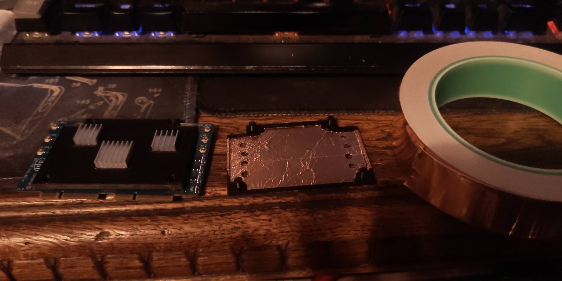
I’d consider using graphite coating instead of foil, the same used for shielding cavities in electric guitars.
1 Like