shield needs to be grounded
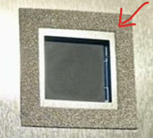
Please cover the side flanks:

For shielding AND cooling (EMI foam):
was also considering using flat brass sheet, with only the skirt printed. or make it even simpler. the skirt could be hotglue, except for a few wire risers soldered between the shield and the gnd pads. anything to take less tooling, not that i don’t have access to all the relevant tools, just refuse to build a die fixture for a oneoff
I’m afraid that the information provided to you by the seller is the closest to reality. It is a problem with the power amplifiers.
Join me in these investigations:
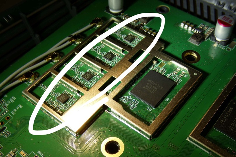
This is a picture of the 2.4GHz RF part of an AX router. The main chip (MediaTek MT7976GN) is visible and the four RF Front-End Module (FEM), i.e. the dedicated power amplifier chips (KCT8239SD), are also clearly visualized:
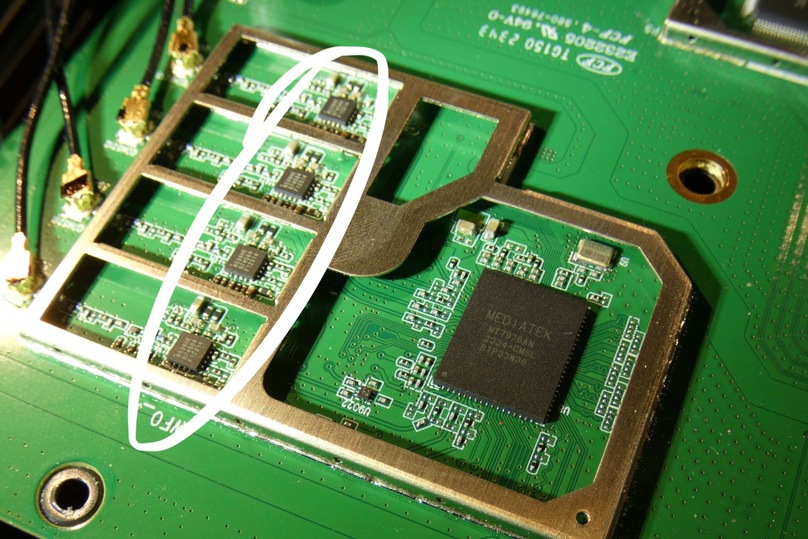
Now, the RF part at 5GHz, with dedicated MediaTek MT7976AN chip and its four dedicated FEM/power amplifier chips (KCT8539HE FEM):
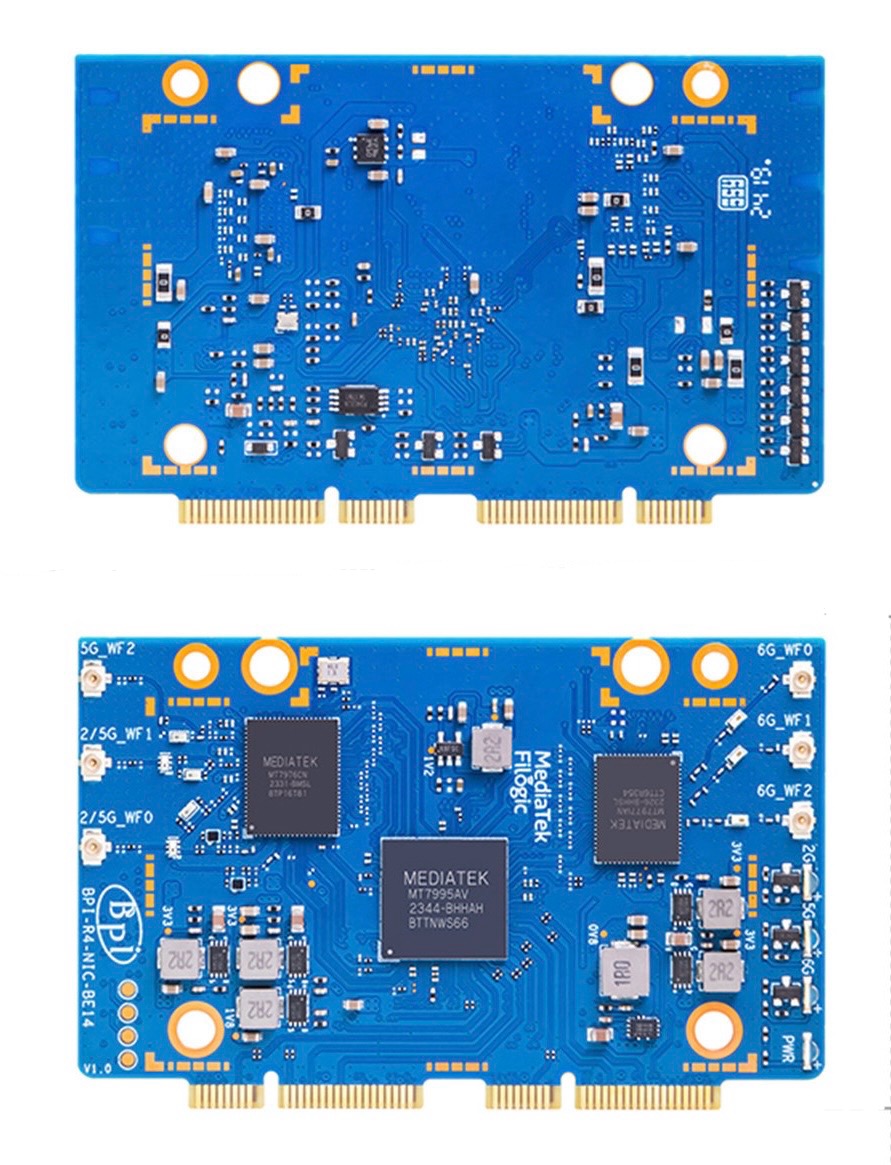
If we take a look at the picture of the BE14 board:
Both front and back, no FEM is displayed, so these chips appear to carry eFEM and as many have already found, the performance of this module can exhibit highly variable range. That is, they work this way by design, as the vendor indicates.
The question that should be asked is:
Is there a possibility that, through drivers or EEPROM firmware, they will improve the management of the eFEM (embedded Front-End Module, also known as integrated power amplifiers) of the BE14 board?
If not, do we know if SinoVoIP will release an improved revision of the eFEM chips or will they make a dedicated FEM design instead?
You haven’t actually investigated anything, this is all well known from beforehand the issue isn’t in the range it’s rather the noise (excluding boards with 7dbm limit bug)
IMO the BE14 “as-is” is a lost cause. It’s become crystal clear, as your post shows, that the real issue is the hardware itself.
I have no idea if it was done on purpose or not, but it’s just not designed to the same standards that an off the shelf router would be. That’s why everyone’s attempts at shielding, including my own, have made no difference at all.
If we want anything useable from the BE14, the real and slightly crazy question should be;
Is it possible to design a separate PCB to add the proper FEMs?
It’s actually really funny I logged in and saw your comment because I have been thinking;
This led me to doing some research into filter and amplifier circuits, though I should mention I am definitely not an expert in this area!
But ultimately this led me to a resounding…maybe.
Since the issue is both noise from the BE14’s poor design and weak amplifiers, this led down a pretty interesting rabbit hole. And anyone who knows more about this please feel free to chime in.
The idea is a small custom PCB, the R4 even has additional mounting posts on the bottom that are unused.
My example included only components for 6GHz. The same would need to be done for the 2.4/5Ghz connectors as well. Each antenna would have its own circuit. (Just like what’s shown in your pictures above).
The idea may be totally asinine for all I know, and I cannot stress enough that dealing with RF and PCB design are not areas I’m an expert in. All I can say is theoretically the idea seems sound, and all of the components can be bought on Mouser for under $5…
Or, maybe Sinovoip will release the BE19, and it could have these issues fixed? Then it could be packetized with the needed extra antennas and cables as an upgrade for the BE14 kit.
Very interesting…
It reminded me of these gadgets:
Anyway, these are gadgets that require external power for each antenna. Killing flies with cannons, totally exaggerated. I do not know to what extent they do or do not improve the signal.
Your approach of something more integrated is more interesting.
That would definitely be the preferred option. Or even just a new revision of the BE14 with the issues fixed.
I tried to set lower power for wireless by building image with this patch mt7996: Use tx_power from default fw if EEPROM contains 0s by im-0 · Pull Request #968 · openwrt/mt76 · GitHub and it partially makes better (or at least I got such feeling). It does not change in reality, it is possible on the manufacturer’s side in the wrong device design…
Noise from the BE14’s poor design
I have a BPI-R3, and I also experience poor Wi-Fi range and high noise on the board.
Thanks to everyone for the discussion! ![]()
My personal statement about the BE19:
(I may be an idiot, but I’m not a cash cow. ![]() )
)
Maybe I’m seeing this in black and white, since I could just use 2.4G, or 5G, or 5G/6G only. I see the BE19 more as an enterprise board. Does a normal person really need this?
My GL.iNet AXT1800 Wi-Fi 6 router has two antennas. Its Wi-Fi 7 successor also only has two antennas.
Actually, I wanted to argue that Banana Pi designed these boards primarily for software development, which is why no eFEM was implemented.
But the BE19 does have eFEMs. For the BE14, the story turned out badly. ![]()
In fact, we should demand a new version of the BE14 board!
I wouldn’t mind paying an extra 30 or 40€ for a good designed and working router board. But this chinese stuff is just made to look good on paper and aliexpress. Their original software doesn’t work properly, last time i tried. They don’t even care.
Which is pitty. How many boards do you know that support wifi 7, 4/5g modems, sfp ports and even nvme slots?
Sinovoip could have this going so much bigger. 10x more successful, but… They just don’t care.
“How many boards do you know that support Wi-Fi 7, 4G/5G modems, SFP ports, and even NVMe slots?”
That’s exactly the problem!
To be honest, I’m waiting for more reports about OpenWrt too ![]() .
.
But there’s another issue: This is just a board — a development board — a router development board. But it’s not a router! A proper router would have shielding, cooling, and a case with ventilation holes.
I never saw this as just “Chinese stuff”. It doesn’t matter where it comes from. The missing eFEM (on the BE14) wasn’t an engineering mistake — it was intentional!
I think better communication about Banana Pi’s actual target audience, and a personal explanation from the engineer who designed the PCB, would help avoid false expectations.
After years of reading about the various issues, I’ve come to the conclusion that the main purpose of these boards is software development. Someone who’s working on drivers or kernels doesn’t need long Wi-Fi range — and probably doesn’t care about RF noise either. → In that context, everything works very well!
You could even argue that this is a very smartly designed board. The case, pigtails, antennas, and power supply aren’t included — and that’s fine!
Honestly, I think Banana Pi should have never bothered with those extras. Trying to provide them creates the false impression that this is some kind of “IKEA router” — just screw it together and it works. Unfortunately, Youyeetoo is doing exactly that — and charging a lot for it.
Last year, I discovered that the newer Turris Omnia includes an SFP port. I’m also keeping an eye on the (Adtran) SmartRG SDG-8734. If we’re not aiming for an “all-in-one” solution, there may actually be some good options out there.
So far, I don’t consider the R4 a dead project.
I’m still waiting for more feedback on the AW7916 and AW7990 ![]() .
.
in that way… honestly, sinovoip should clearly state this in the product description, right at the top:
“No official software support or updates. Driver development is community-based. Due to hardware limitations, the ideal WiFi 6 range may only be 1–3 meters. Most WiFi 7 features are just not work, typical starting speed at 30~50Mbps.”
Otherwise, people will seriously start questioning their own skills when setting this up — even those of us who are fairly experienced with OpenWRT. It’s misleading, and a clear disclaimer would help set expectations and avoid frustration. most important, save a lot of people’s time include mine xxx+ hours😂
Right now, I’m waiting for a device from another vendor. They’ve already released one model — it’s somewhat limited (IPQ5312, BE3600, and only 2.5GbE), but promising.
In their community group, they’ve shared plans for several upcoming devices. One of them is based on the IPQ5322 platform, featuring tri-band support including 6GHz, 10G SFP+, 4×2.5GbE, PoE output on LAN ports, and PoE input on the WAN port — meaning it can be powered with just a single Ethernet cable. They also mentioned future NAS / 5G CPE version.
What really sets them apart is the partnership with iKuai. Their current device (IPQ5312, ~288 RMB) ships with the enterprise version of iKuai firmware preinstalled, ready to use out of the box. It also supports booting OpenWRT from a TF card, with the community already release a QWRT build (OpenWRT with Qualcomm’s proprietary SDK, drivers, and hardware acceleration). If a TF card is inserted, it takes boot priority over eMMC; otherwise, it boots from the internal emmc.
I won’t mention the brand just yet — I’m waiting to get my hands on the hardware and test it in real-world conditions (especially WiFi performance and whether MLO is actually functional and stable.) (![]() for… hopefully saves others some time
for… hopefully saves others some time
Is it possible to connect the BE14 module to PC?
Believe me, you’ll definitely be disappointed — most Chinese company only care about making quick money and don’t treat their work as a true career.
I respectfully disagree.
What case would make you more motivated to develop software? Developing software for a board that you know, when it will be ready, will be a major kick ass and stable board, or a lamely, craply designed one that you know for a fact it will never be the dream board you desire for your network?
I guess any company wouldn’t mind have 10x more success. Imagine a fully working and stable banana pi router instead of wasting 500 ou more euros/dollars for a big brand router.
Raspberry pi is also a development board, look at its success.Raspberry does the right thing, banana does not. That’s the difference between success and fail.
Thanks for mentioning those brands. I really was looking for that kind of stuff… Unfortunately, none of those boards support dual wifi slots (for 2.4 and 5ghz). Please correct me if i’m mistaken.
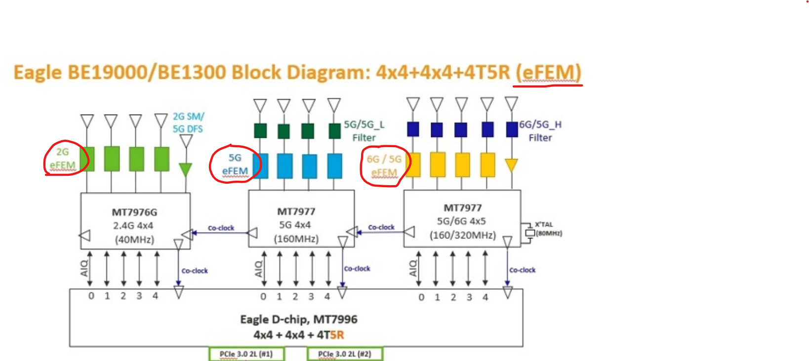
P.S. - Does cards like MT7922, MT7925, etc, have that eFEM?
I was very excited to have found in the BPI-R4 a board that integrated everything I need, in a compact design and with a single governing chip providing everything: 2 SFP+ 10Gbit, 4 RJ45 Gb, PCIe ports for NVMe SSD, Wi-Fi and 5G.
I purchased two AsiaRF (AW7916 and AW7915) thinking to avoid the problems of the BE14, but I have to say that the performance is completely disappointing. I feel like I’ve thrown my money away.
Which makes me think that the Wi-Fi problem rather than being in the boards, both the official and AsiaRF boards, is in the design of the BPI-R4 board itself. Either it is an amateur electronic design, or the tracks are not properly electrically isolated. Either the electronic components are not of high quality or they are insufficient. I have no explanation.
So before I had 3 devices (x86 box, ONT, AP), I went to only 1 (BPI-R4) and finally I have resigned myself by adding again the AP.
I was probably abducted by how complete it is, the all-in-one integration possibility it offered me and that I thought it was made with Mediatek backing, but I should not have bought a development board (both software and hardware).
Just to chime in on the noise. Using the bpi-r4 without the provided metal casing - especially the top lid - results in the router being practically unusable.But with it, it’s just fine. But yeah, there appears to be some interference being emitted. Using BE14, nvme, standard metal case, heatpads on the underside of BE14 making contact with the case’s underside, and an aluminium slab of a heatsink on top of the lid to additionally dissipate heat. But yeah, acrylic cases are definitely not an option if the intent is to daily-drive this.
Thanks for the reply! ![]()
“What case would make you more motivated to develop software? Developing software for a board that you know, when it will be ready, will be a major kick ass and stable board, or a lamely, craply designed one that you know for a fact it will never be the dream board you desire for your network?”
I’ll try to give you a short answer: I think I want what you want ![]() → a good hardware platform with working software
→ a good hardware platform with working software
What is the purpose of the board? I think it is not about delivering a finished router to the end customer.
The software development is done for the whole MediaTek platform.
I assume the industry can get a first impression of what they are dealing with (MediaTek marketing strategy?)
The open source community could get its hands on the platform long before the first routers are published.
That we get what we want is just a coincidence (best case)! ![]()
"I guess any company wouldn’t mind have 10x more success. Imagine a fully working and stable banana pi router instead of wasting 500 ou more euros/dollars for a big brand router.
Raspberry pi is also a development board, look at its success.Raspberry does the right thing, banana does not. That’s the difference between success and fail."
“Thanks for mentioning those brands. I really was looking for that kind of stuff… Unfortunately, none of those boards support dual wifi slots (for 2.4 and 5ghz). Please correct me if i’m mistaken.”
P.S. - Does cards like MT7922, MT7925, etc, have that eFEM?
*? I’m not sure that eFEM are the “main problem” may be noise is more responsible … . Someone who wants to supply a house needs both working well …