i have 20cm and its too long. 3 could be 20cm for those antennas more far away but 3 should be 15cm for those that are close to the case, otherwise you will have some cable loops. also keep in mind that those are a bit stiffy, which makes those loops even worse. i bought these https://www.amazon.de/dp/B0B9RXM7TB and it mades the noise even worse.
They do a great job. They release a defective module to the market, and instead of including a fix in the firmware, they tell people to install it manually. The situation is approximately the same with the 8gb ddr board versions.
What is wrong with 8gb versions? Only bl2 has to be replaced to drive the ram differently compared to 4gb version,thats all.
just collecting different fixes to get a normal working device is a process that can be avoided by placing them in the official firmware for the device, or am I wrong?
This doesn’t do much in terms of noise it’s still The same for me
Openwrt mainline isn’t officially by BPI, Openwrt MTK is
I just recently started to delve into openwrt and still don’t understand the specifics. What is the chance that these fixes will appear in the firmware for BPI R4? which I take from https://firmware-selector.openwrt.org/ Or will I have to constantly apply patches when updating?
They’ll add it to Openwrt at some point
Just noticed i bought the wrong ones. I thought i have the correct ones because they fit. I was wondering why i have so much noise now (-76db from before with -85db) so i measured the cables resistor. It was with the old cables from sinovoip 16mOhm and with the new ones 11mOhm, so the new ones should be better. But while measuring i noticed, the ones from sinovoip are male and the ones i bought are female. i copy pasted the text from here to amazon and did absolutely not check the sex. I am wondering now if it would make sense to buy the correct cables or buy new antennas (males), or if this does not matter. I measured also the outer part of the cable and got the same resistor-results so i could imagine this does not matter. Anyone familiar with that?
Cable and antenna have to match,either antenna or connector need to have the “pin” poking into the other side. Having both sides without pin does not have a complete connection.
would you buy new antennas or new cables? ^^ both cost the same, more or less
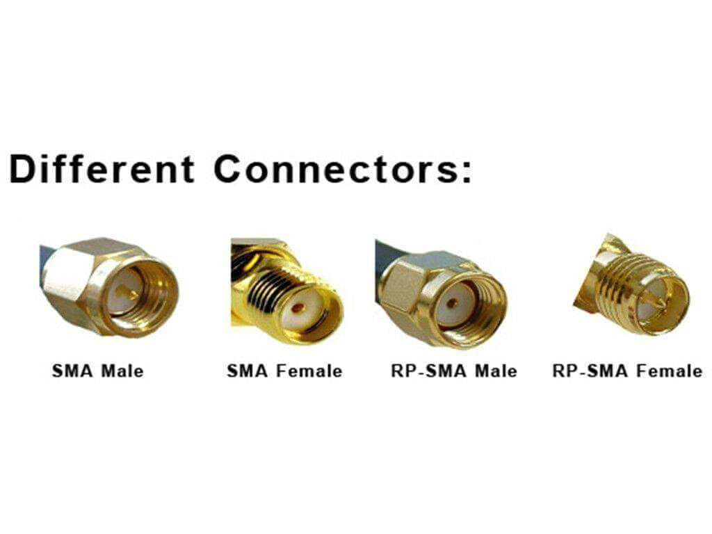
Should not really matter…antennas are more material than the cables,but i prefer having the “pin” on the cables and hole on antennas (rp-sma cables).
“Pin” in antenna connector end = RP-SMA
No “Pin” in antenna connector end = SMA
The stock cables and antennas on BPI-R4 are RP-SMA. I just canceled an AliExpress order because I accidently ordered SMA as well, and not RP-SMA.
1 Like
I had a thought. Could the stock 12v 5a power supply included with the BPI-R4 kit be the cause of excess noise? Has anyone tried a different one, or possibly power it via USB-C PD and seen any difference?
Or something like this?:
I have a type-c kit with a native power supply. There is also noise.
Perhaps the device needs grounding. I am not an expert in this topic, but I assume that because the case is metal, and in fact, connecting the antennas and the board to it creates a common grounding circuit and the antennas pick up this interference. I wonder what will happen if I try to leave the board in the case, but take the antennas outside of it and ensure that the wires and attachment points are not in contact with the case. (This is unreliable information, but only my attempts to reason)
It is also worth understanding that there is grounding, which should divert interference to the ground. And there is zeroing (GINA, zeroing, vanishing - I don’t know how it is correct in English) which does this on the device case, which should then be grounded (but it is not a fact that this happens and interference remains on the case). In my language, 2 different terms are used for this, but the translator tries to translate everything as grounding.
Mine is powered via usb c
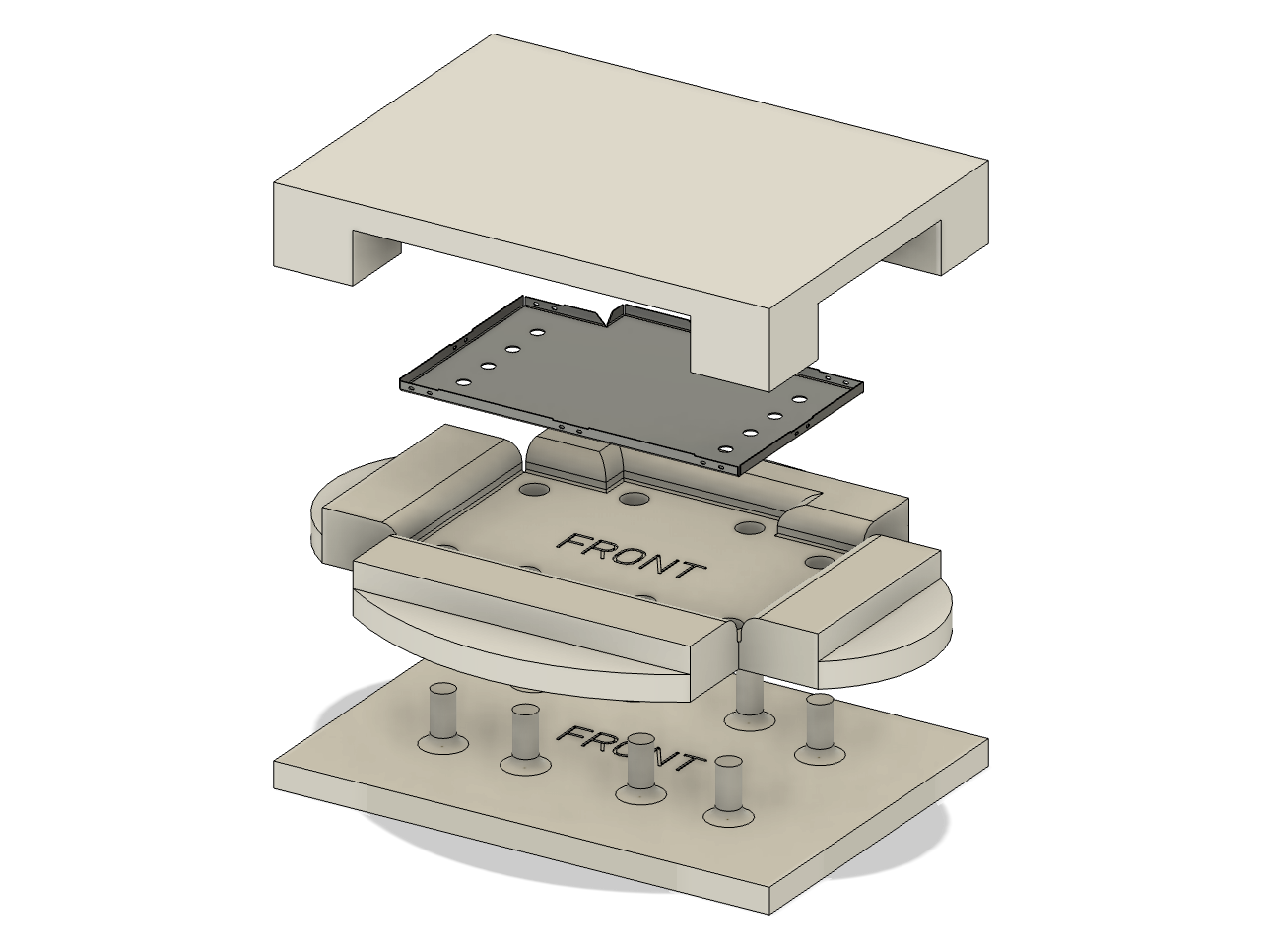
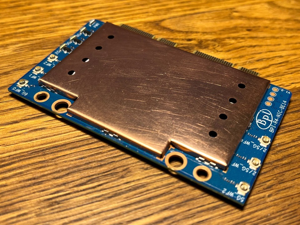
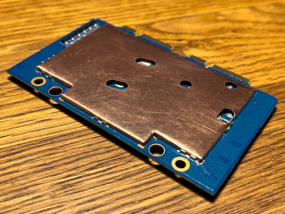
I designed a 3D-printable die set for pressing EMI shield cans from (preferably, laser-cut) blanks. The model and the instructions are on MakerWorld. Some final tweaks to the DXF drawings of the blanks (included in the project). Again, adding EMI shielding to the BE14 won’t do much for mitigating the internally generated interference. Regardless, it’s a good idea when using a plastic case. The top shield can also provides a flat surface to mount a large heatsink on.
2 Likes
Please tell me what size of cooling radiator you use.
40x40x10 copper fits nicely and is more than adequate for cooling the ICs.
