Hi, do you think it could be the DCDC converter itself with its switching frequency inside the IC or the ripples on the output that are interfering the wifi ICs? For the first a shield should help, for the second additional capacitors / inductance?
It could be either or both, but I’d lean toward EMI coming from the 3V3 regulator UP3 (MP8759) as I said above being responsible for a lot.
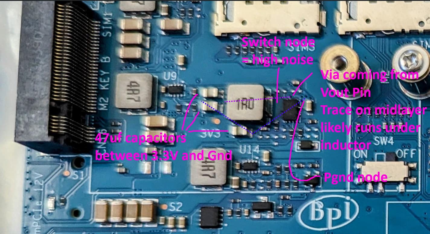
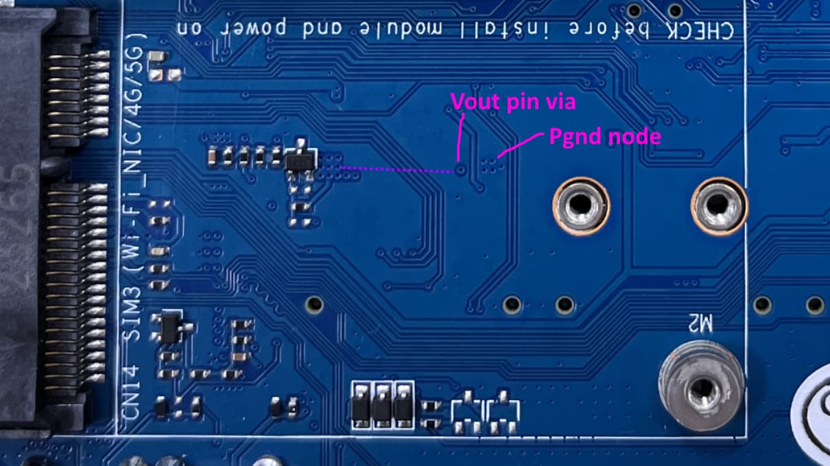
Looking at the layout I think that there could be noise radiated out of the bottom of the PCB, and/or coupled into the four traces that cross the purple line I have drawn. Usually it is best practice not to have any traces run underneath the switch node and inductor. The switching frequency of MP8759 is 700kHz in continuous mode, but the ringing at the switch node in discontinuous mode will be higher frequency and probably has more effect on the wifi ics on BE14. The return path between the 47uf capacitors and MP8759 Pgnd also seems quite long, but I can’t see what has been done on the midlayers. I would have also included a smaller value capacitor in parallel to improve the high frequency smoothing.
1 Like
Ig there’s no way to fix this from user perspective end. Only BPI can fix this ig
Which will not help any existing users/owners, unless BPI will issue a ‘recall’ and fix older boards.
Yep, so we’re stuck unless BPI deals with it
I soldered the shield clips onto the board and made hand-cut shield cans out of copper and brass to test out.
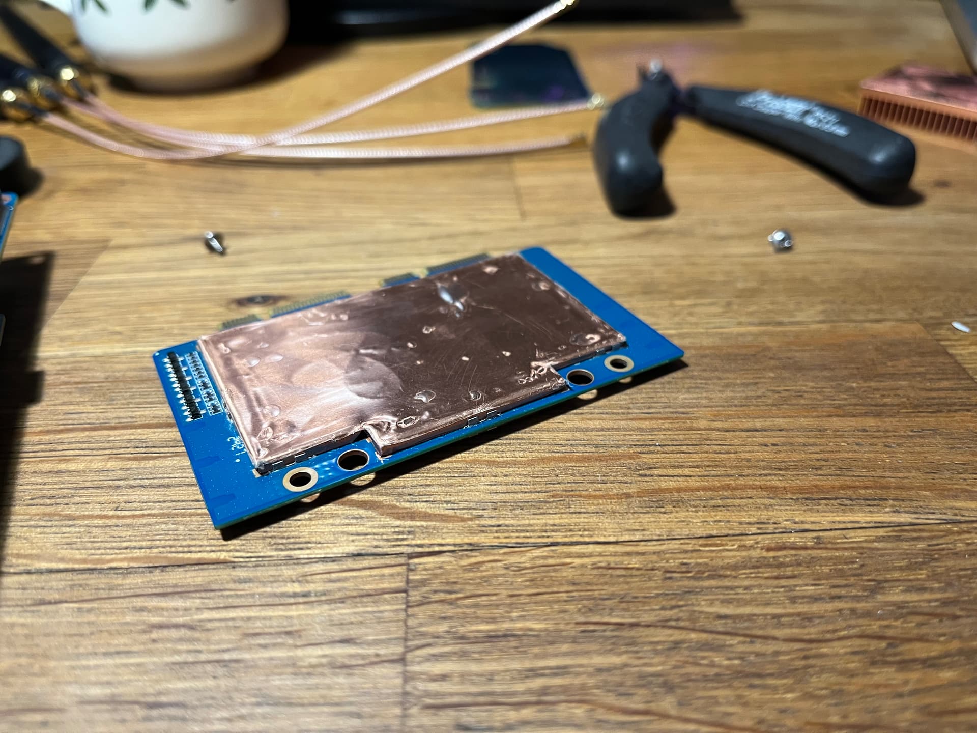
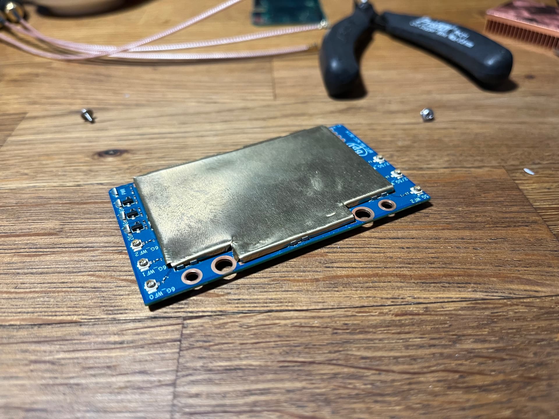
Results before shielding:
- no pigtails, no SFP: -89 dBm
- SFP cages populated: 91 dBm
- pigtails (20 cm) and antennae connected, no SFP: -85 dBm
- pigtails, antennae, SFP: -89 dBm
With shielding on both sides:
- no pigtails, no SFP: -90 dBm
- pigtails and antennae added: -87 dBm
- pigtails and antennae, SFP: -90 dBm
- everything put in the stock metal housing: -82 dBm
The shield cans I made weren’t perfect and left small gaps between the metal and PCB. Still, pretty disappointing. As a conclusion, protecting the pigtails by routing them away from the mPCIe slots (which I did for all measurements), populating the SFP cages and ditching the stock metal housing works well enough. Adding EMI shielding on top of that seems superfluous. Although, I’ll order the new cans to be laser-cut to see this project through to the end. If anything, the top shield makes cooling the ICs easier. It also should help with external EMI sources such as other Wi-Fi station.
As for the power lines, I only checked the ripple on the +12VD (both coming from the USB PD circuit and on mPCIe slots), which was rather high at ~150 Vpp. I managed to cut it down to ~110 Vpp by adding 47 and 0.1 uF caps in parallel, but that didn’t affect the Wi-Fi noise level.
2 Likes
Thanks for the advice. I’ll try adding a ceramic 0.1 uF to the 3.3V line and see if it helps. Also to the 12V line after Q16 feeding the BE14 in parallel with C50 and C51, but I have yet to find a good spot to solder to.
Welp that’s sad to see it didn’t go well
How did you add the capacitors can I see that
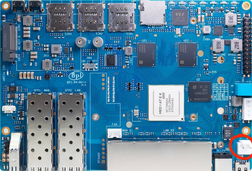
Ah ok, I use a usb c PSU to power my router
To be clear, this connector is tied to 12V regardless of the power source (DC barrel jack or USB PD).
Oh ok i didn’t look at schematic so didn’t know that was connected too
and the noise-levels are as reported by luci?
Yes. I left only the 5 GHz station up.
Nah, the extra 0.1 uF cap on the 3.3V line didn’t impact the Wi-Fi noise. Didn’t check the ripple with a scope, so it still might be worth it, as there are other devices on the 3.3V line beside the Wi-Fi NIC.
I’m probably going to.buy some caps to reduce ripple
My noise for 5ghz is -84dbm and -83dbm on 6ghz that’s with Taoglas antennas and both SFP slots populated
I may need to move the antenna cables so they point away from the WiFi card
I wonder what would happen if you put 2 47uf caps
I tried 100 uF with roughly the same result.