Since I don’t have a R4 on hand to test, can someone tell me if the two posts used for screwing down the BE14 are connected to the ground plane? I assume they are and was wondering if using tape and plastic screws so that the R4 ground plane and BE14 ground plane don’t connect through them makes any difference, better or worse.
I’d also be curious to know if a copper foil shield, taped to the bottom of the R4 PCB and soldered to the R4 ground plane specifically, makes any difference.
Yes exactly, I am saying that the SFP modules drawing power from the regulator is why it might be quieting the noise down. Nothing to do with the SFP cages being grounded or acting as shields themselves
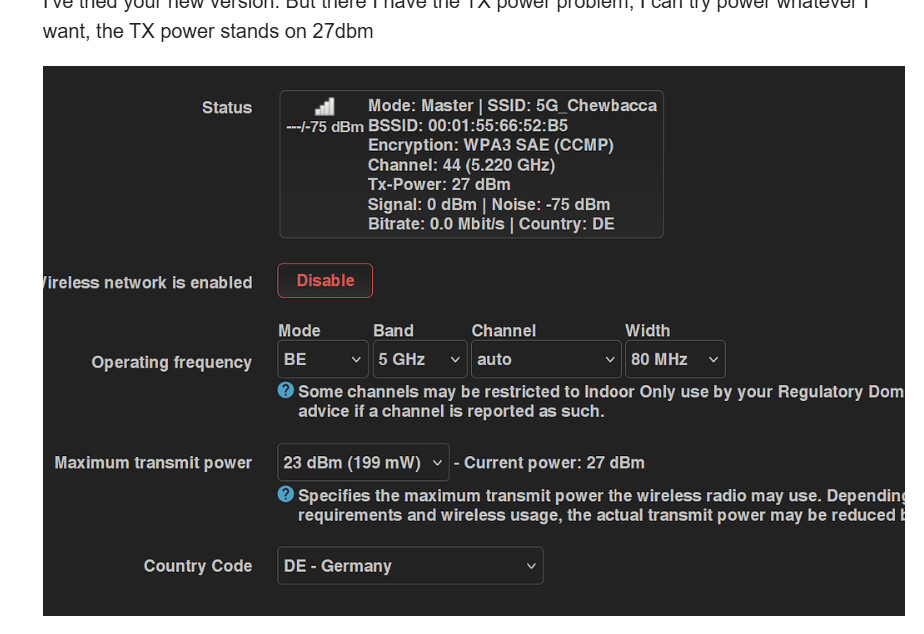
Tbh tho I don’t think the SFP makes a difference, I got 2 filled slots and I still get -85dbm when 6ghz is at 80mhz width and -81dbm when at 160mhz probably even less at 320mhz
Also, as mentioned in openwrt-forum, the value reported in LUCI/webgui might not be the correct noise value (all 3 bands always report the exact same noise level…), I now measure noise using the cli:
iw phy-2g survey dump | grep -B 1 noise
(replace phy-2g with the name of your device) - strangely (and probably the cause for the luci error), even if I only specify 2g-device, it reports noise for all wireless-channels:
BPI-R4 seems to report the noise value for the last AP on the list. So, it’s important to turn off the 6 GHz band when, e.g., trying to find the best channel for 5 GHz.
Thank you for your input. Do you think it’s possible for the noise to leak through the 12V power circuit, too? The filtering on the BPI-R4 looks rather bare-bones to me. I could take a look at the ripple with an oscilloscope, but I’m not sure what PtP range would be considered normal for this application.
Yes it’s certainly possible for this to be the case. For telecom power supplies about 100mVpp would be typical.
That said, it also depends a lot on what frequencies are present. Any harmonics through the 5GHz band will have a big impact
Hi,
do you think it could be the DCDC converter itself with its switching frequency inside the IC or the ripples on the output that are interfering the wifi ICs? For the first a shield should help, for the second additional capacitors / inductance?
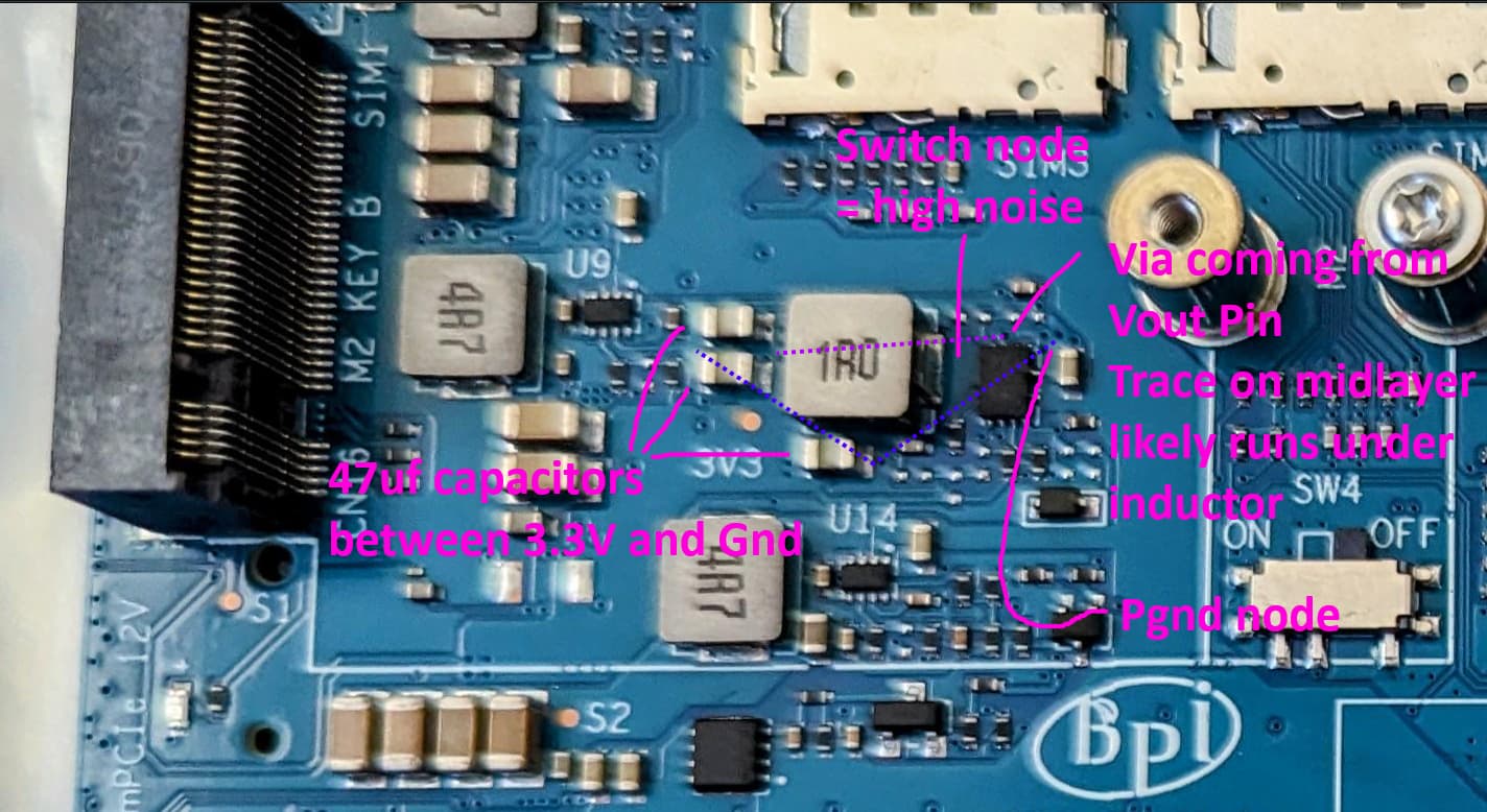
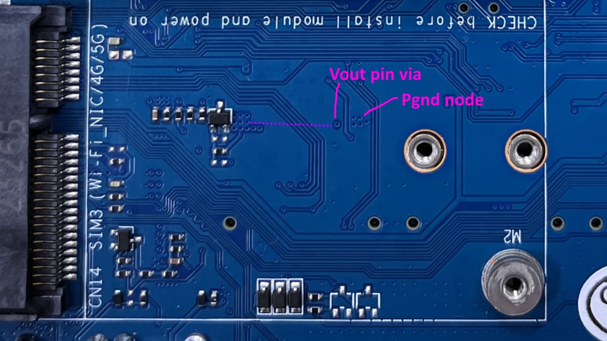
Looking at the layout I think that there could be noise radiated out of the bottom of the PCB, and/or coupled into the four traces that cross the purple line I have drawn. Usually it is best practice not to have any traces run underneath the switch node and inductor.
The switching frequency of MP8759 is 700kHz in continuous mode, but the ringing at the switch node in discontinuous mode will be higher frequency and probably has more effect on the wifi ics on BE14.
The return path between the 47uf capacitors and MP8759 Pgnd also seems quite long, but I can’t see what has been done on the midlayers. I would have also included a smaller value capacitor in parallel to improve the high frequency smoothing.
pigtails (20 cm) and antennae connected, no SFP: -85 dBm
pigtails, antennae, SFP: -89 dBm
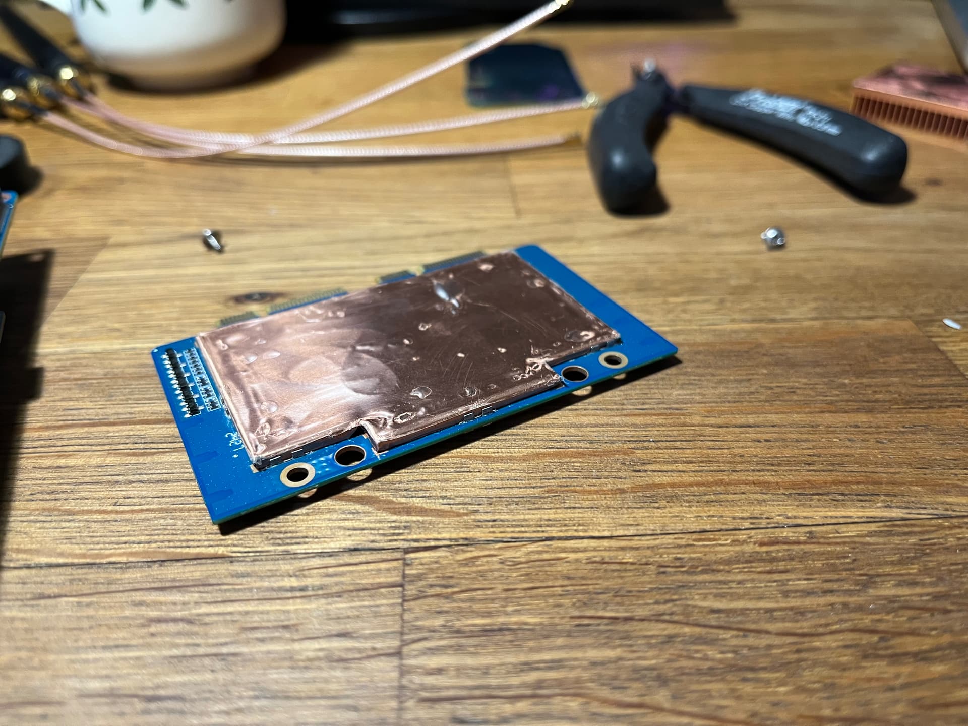
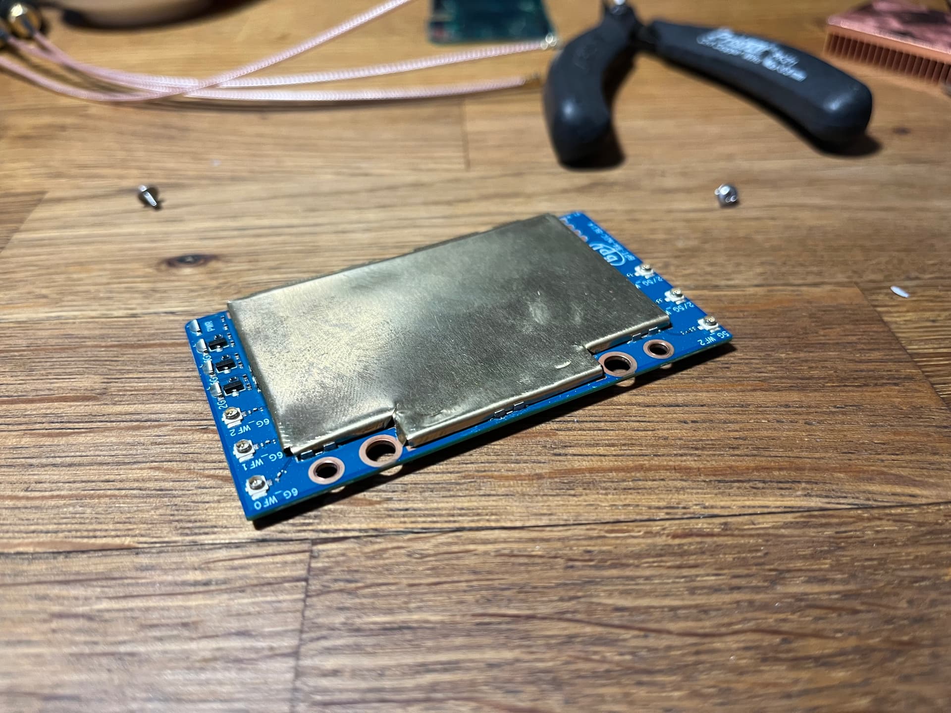
With shielding on both sides:
no pigtails, no SFP: -90 dBm
pigtails and antennae added: -87 dBm
pigtails and antennae, SFP: -90 dBm
everything put in the stock metal housing: -82 dBm
The shield cans I made weren’t perfect and left small gaps between the metal and PCB. Still, pretty disappointing. As a conclusion, protecting the pigtails by routing them away from the mPCIe slots (which I did for all measurements), populating the SFP cages and ditching the stock metal housing works well enough. Adding EMI shielding on top of that seems superfluous. Although, I’ll order the new cans to be laser-cut to see this project through to the end. If anything, the top shield makes cooling the ICs easier. It also should help with external EMI sources such as other Wi-Fi station.
As for the power lines, I only checked the ripple on the +12VD (both coming from the USB PD circuit and on mPCIe slots), which was rather high at ~150 Vpp. I managed to cut it down to ~110 Vpp by adding 47 and 0.1 uF caps in parallel, but that didn’t affect the Wi-Fi noise level.
Thanks for the advice. I’ll try adding a ceramic 0.1 uF to the 3.3V line and see if it helps. Also to the 12V line after Q16 feeding the BE14 in parallel with C50 and C51, but I have yet to find a good spot to solder to.