Hi, i have the heat sink with fan from sinovoip and it works. But the sfp+ ports are getting hot as hell, so i thought i’ll replace the stock fan with another one from noctua and also put one noctua on both sfp+ ports. I ordered this cooler NF-A4x10 5V and its awesome. I would love to use one of those, but… i have no idea how to get it working with PWM. I thought the pin layout is something like: + - pwm, but frank told me thats “sense” or something like that (no idea what this is tbh, i am java dev, not embedded dev).
When i connect that FAN it spins with full speed which is clearly hearable (i live next to the router, maybe 2m is my main sitting location from my home cinema). When i run that FAN with ~3.5V its impossible to hear and still produces a lot of cool air. The FAN starts at ~2.3V spinning.
So i thougth… maybe there is some way to get a 3.3V from the board or somehow use the “pwm”. But all noctua FANs with PWM have 4 pins, not 3.
Anyone an idea?
To control the pwm of this fan, the board needs to apply pwm to the supply pin.
A 4 pin fan, only a pwm signal (low current) can be send to the fan. Inside the fan electronics, the high current of the fan motor is switched, according to pwm signal.
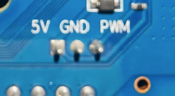
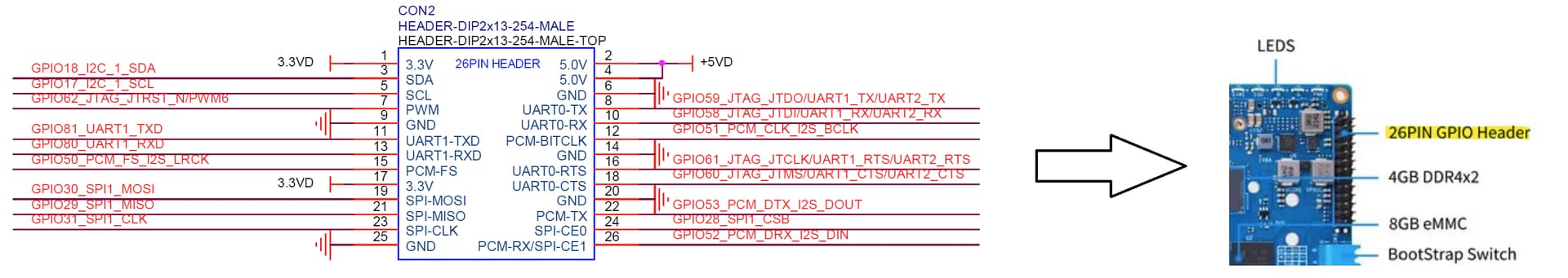
Ok, so that means the schematic/picture is wrong, because it states: File:Banana Pi BPI-R4 interface.jpg - Banana Pi Wiki - 5V Fan with PWM on PH-3PIN.
Is there any way to get that pwm signal from the board? Or do you see any other way to get a silent system? Is it reasonable to create a little circuit so i get 5v->3.5v from PH-3PIN and use that as supply for the noctua?
Can you explain me how this works when the pwm signal is sent to the supply pin? Does it change the voltage? Or is this some proprietary “signal” hidden behind the voltage? I dont get that…
So when i buy the 4pin variant of this FAN it should work? Should i connect the Vin then to pwm too, so the fan can extract the pwm signal?
If i use this, i must place it somewhere in the case. There is already nearly no space left when i use 2 of those noctua fans. Also not sure where i should get the temperature from. Or do you mean i should use this and set the output to 3.5V? It states fan current: 0.8A. One noctua needs 0.4A (measured on my “laboratory” power supply) - might this become a problem?
Oh thats a nice idea, but i am wondering whats the advantage compared to using 2 resistors and let it run with 3.5V? Because the SFP+ cages are always hot.
Maybe thats a nice idea for the cpu fan. I am already looking to replace the original heat sink and replace it with one that does not have a cut-out. Then i could place the sensor on that and use the controller for the cpu fan. But… when i create a 3.5Vout “component” i could use both FANs and just let them run.
I have resistors and a lot of such small components here now, so i could instantly start.
When i order, i have to wait.
What would you do?
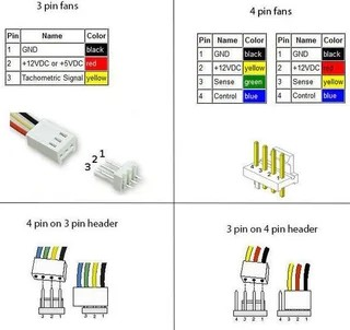
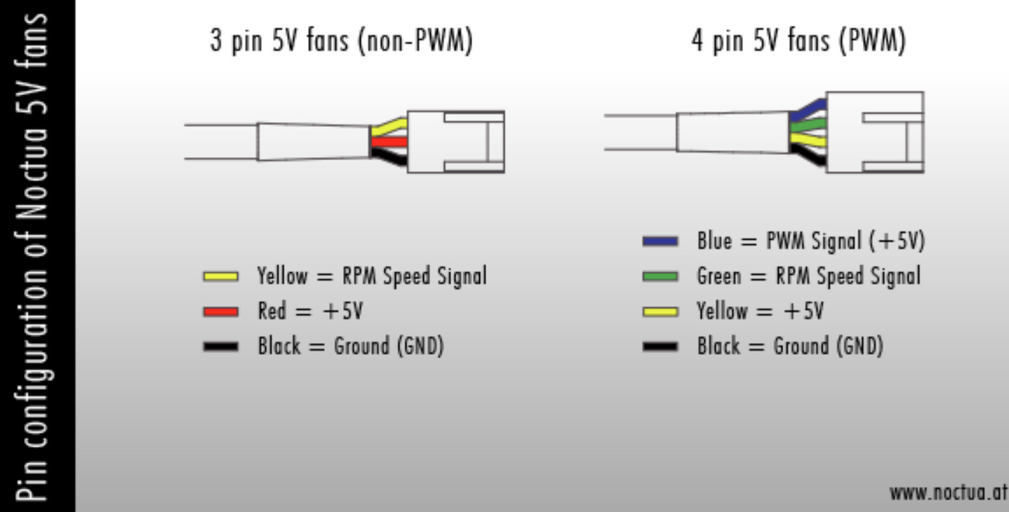
The 3 pins connector on the R4 and the included fan are non standard and have for pinout 5V (red wire) GND (black) and PWM (yellow). Your fan has a RPM signal instead of the PWM like nearly all 3 pins fans. There are two ways to use a PWM signal to control these fans (read the 2nd and following paragraphs of “Controlling Fan Speed” on page 6 of this datasheet). Another option is to buy the NF-A4x10 5V PWM and makes an adapter (I have done just that with a NF-A8 5V PWM mounted on a 3d printed plate to replace the top plate of the case).
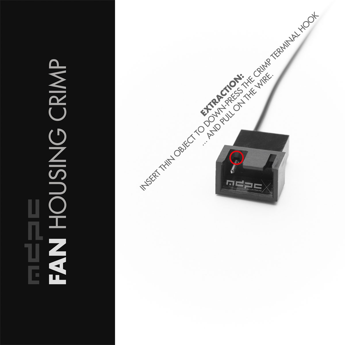
I’ve made the adapter using this cable and a 4 pins connector (don’t forget to check required pins). To remove the 3 pins connector of the cable I’ve used the pins as the thin object in the image below.
Yes, i knew that before my initial posting. But the schematics clearly states “PWM” and not “Voltage controlled”. @TheServer201 mentioned that the 3rd wire of the R4 is indeed pwm, but there seems to be nearly no fans that by default have this layout. I will read further today when i am back from the meeting now.
Unfortunately, it would be better to have 3.5-3.7v, i assume thats the sweet spot (not hearable and max. air flow), not sure if 3.3v would be enough. But i will test that today with gpio and 3.3v as i assume, thats the easiest to achieve compared to creating again jst connectors … i am too old for such small stuff
One noctua requires 0.4A. And i know now what my “goal” is: one fan should be fixed at ~3.6v for the sfp ports (but will try it with 3.3v today) and the other controlled by pwm (if possible) or also at ~3.6v.
Do you know whats the max. wattage is of the gpio pins? Can the 3.3v handle 0.8A?
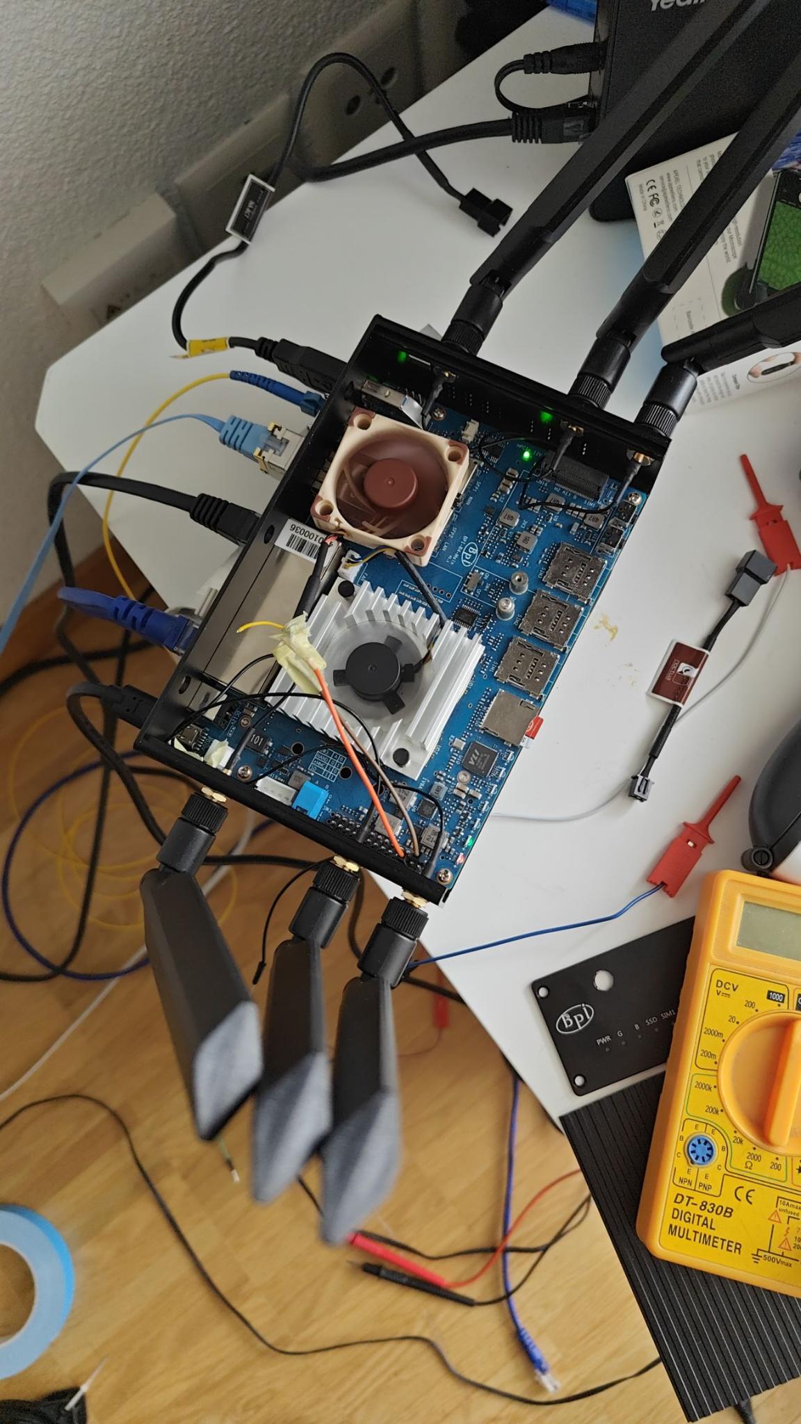
@TheServer201 thanks i will read this in about 7h and probably ask some more questions Can you maybe share a picture of your R4 where your fan is located?
the sfp fan is now working like a charm @3.3v thanks @Lorem_amicus , but i noticed something wierd… when i lay down the fan on the sfp cage, i am somehow unable to get an ip. When i let it “float” a bit (e.g. use the antenna cable to push the fan a bit over the sfp cage) it works like a charm. Anyone an idea what could cause that?
I was planning to use some heat absorber tape to tigthen the fan to the sfp cage, but when i dont get a connection anymore… its a bit useless
small measurements (wip):
43.5°C with case open and oem fan
41°C with case open and noctua fan (on the cpu @3.3v)
50°C with case closed and noctua fan (on the cpu @3.3v)
53°C with case closed and oem fan
52 °C with case closed and oem fan on the cpu and noctua @3.3v on the sfp cage
The noctua was laying on the oem fan so not a real comparison, guess @4v and on a good heat sink it would produce way better results
@TheServer201 what do you use on the cpu? do you use the same heatsink like i do or do you have something else? Can you share a bit information about the pwm-signal-adapter you built?