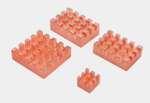
When I was ordering my BPI-R4, I wasn’t sure if the official metal case would be good. Read some rumors that it might be have issues with cooling due to a tight spacing and lacking a design for cooling the bottom part with WiFi board. So I’ve decided to start with a cheap acrylic case I got for ~$3. Turns out it was an option because it seems to have slightly more spacing on the bottom between the board and I could fit 7mm height fan. But not right under the wifi board, where only ~5.5-6mm spacing remains. There are tiny coolers as low as ~3mm available, but they are pretty small in other dimensions, so I did it the other way. I’ve ordered a copper heatsinks for Orange Pi 5, which are ~5mm, and 3 out of 4 in the pack sold have dimensions almost matching dimensions of the chipset ICs. Somewhere around $3 again with shipping.

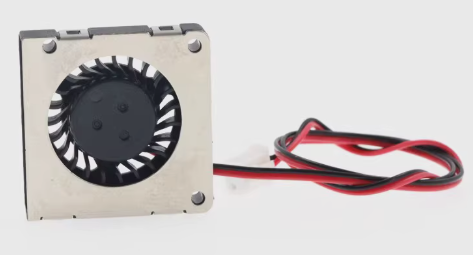
And ordered a 3007 (30x30x7mm) blower fan, with side-out flow again for the $3.

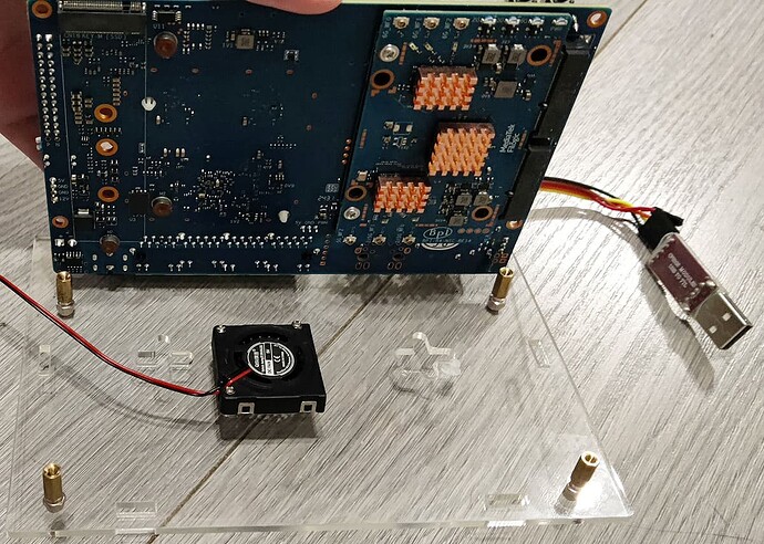
It “catches” air from the front side relative to this picture and blows it out to the left edge. So I’ve installed heatsinks on the ICs and attached fan on the bottom housing plate, slightly before the edge of the WiFi board where it can fin. With the flow out directed towards the installed heatsinks. 30mm side doesn’t covers all 3 completely, but still good at cooling all of them as air get dissipated while hitting the center heatink.
Had to drill a hole in housing for the fan air intake. Used a screwdriver with a conic drill. I’m not good with a “handcrafting skills” so ended up with 1 crack but I don’t care as it’s the bottom part which is not seen anyways and it’s still solid and didn’t lost much of the integrity from that crack. Most likely if drilled slower, and applied less tension it would have turned out more neatly. But as I’ve said - I’m not good at it and I’m just fine with the result. Fan are attached with a M1.4 self-tapping screws straight to the housing.
I’ve reversed direction of the hex stands included with the case, so that the rounded “caps” become a housing “legs”, adding some space below it for air intake. Should probably add some dustguard as well but mine are currently seating in a pretty clean environment so I don’t bother for a while, will add it some days later once I’ll find something suitable.
Had a readings of ~67-68 *C from the WiFi module on the board without casing, i.e. open (at the room temp of ~24*C). Without a load, but all 3 APs running. Same environment and conditions but having it inside the housing and aux fan running gives me ~41-42 *C, which I consider could call a success.
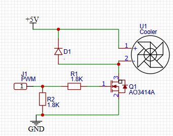
The fan I’ve used are not PWM capable itself. But I’ve added an external MOSFET circuit to allow controlling it. Because at the full speed the sound are pretty noticeable. It’s not that load, but still.
BLDC fans without own PWM pin usually can’t be controlled with PWM, like a fans with a PWM wire (which in fact have similar circuit inside, but it’s wired only to a motor, not the logic part which needs constant DC supply), but keeping a PWM frequency pretty low (< ~1 kHz) still works and allows to control the speed of this fan to a certain degree. I don’t hear any additional noise or vibrations coming from this low freq PWM and the noise from a fan itself becomes nearly unnoticeable at PWM levels < ~50%.

Needs a MOSFET with low Vgs(th) and preferably a low input capacity. I’ve used dmg2302uk I’ve had lying around but something much more common, like AO3414A can be used as well.


