Hello,
but when you don’t have /sys/class/thermal/thermal_zone0 how do you check the temperature?
Thank you.
Why don’t you have this? Which kernel/image do you use?
It is possible to measure with infrared thermometer,but this is only outside temp not internal chip temp which would be a bit higher.
I’m building my own image with OpenWRT from the 24.10 branch and the MTK SDK. I can see and control the PWM fan but I don’t get the thermal_zone0, only a bunch o cooling_devices. Any clue?
i guess dts there misses thermal_trips or option hwmon_* is missing
Uhm, interestingly, I built an openwrt image (24.10 branch) without the MTK SDK/feeds and the thermal_zone0 is there.
I also assumed that SDK provided some better support for the wifi card but… that’s not the case so now I wonder why do I need include it anymore…
Interesting, but somehow expected - MediaTek tends to initially implement things “their way”. I don’t think there are any advantages on using MTK feeds/SDK right now, as upstream has nearly every feature ported right now. Probably only WED and ipsec crypto offloading which was recently added on the MediaTek git, but WED are partially supported by the upstream already.
Last time I’ve compared vanilla OpenWRT build and older OpenWRT with 5.4 kernel from Sinovoip, the one with proprietary WiFi drivers - upstream OpenWRT snapshot got me about 10% better WiFI throughput. And that 5.4 branch was supposed to have more advanced WiFI driver (the one with proprietary blobs I guess), at least it had MLO and was more feature-complete.
But probably even if it didn’t had thermal_zone, maybe /sys/class/hwmon/hwmon0/temp1_input was available?
Side-question: Anyone knows if there is a way to add/modify thermal zones on the installed system without having to modify device tree files?
You can temporary override values from devicetree like this: https://wiki.fw-web.de/doku.php?id=en:bpi-r4:start#testing_fan
In my case I need to add new thermal zone. No device tree node exists so far, so it’s not exported to the sysfs interface.
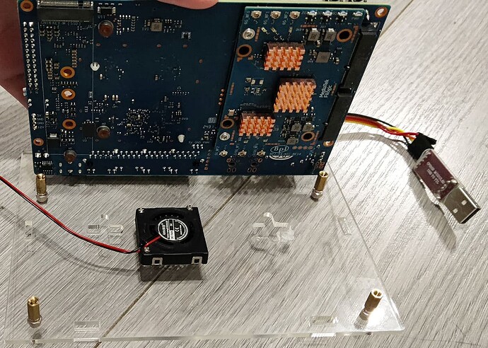
I’ve modded my BPI-R4 to add a secondary fan for WiFi module cooling. Connected PWM signal to the PWM6 channel exposed on the GPIO header. Works good so far if I manually setup pinmux/PWM, as I’ve noted above. Can control it that way via user-space daemon, but would prefer to have kernel hwmon module to manage it. Straight approach is to add required nodes to the device tree, but I’m looking for a way to be able to stick with vanilla OpenWrt kernel/images. Maybe there is a way to add a kernel device tree overlay outside of the FDT image? Or create a new nodes from running OS, or maybe add a new hwmon/thermal zones, not included in the booted device tree.
PS: @frank-w, I’ve noticed you’ve linked my post from your wiki. Feel free to use/copy/modify information from my post, if you would like to include it on your website “inline”, not as a link. No credits/link/etc necessary. You have valuable information there, thanks for your research and sharing!
how did you managed to add a second fan to the wifi module ? what kind of enclosure you are using?
would you mind to take a pic ? thx
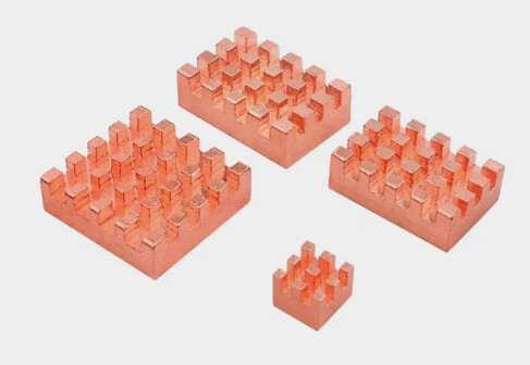
When I was ordering my BPI-R4, I wasn’t sure if the official metal case would be good. Read some rumors that it might be have issues with cooling due to a tight spacing and lacking a design for cooling the bottom part with WiFi board. So I’ve decided to start with a cheap acrylic case I got for ~$3. Turns out it was an option because it seems to have slightly more spacing on the bottom between the board and I could fit 7mm height fan. But not right under the wifi board, where only ~5.5-6mm spacing remains. There are tiny coolers as low as ~3mm available, but they are pretty small in other dimensions, so I did it the other way. I’ve ordered a copper heatsinks for Orange Pi 5, which are ~5mm, and 3 out of 4 in the pack sold have dimensions almost matching dimensions of the chipset ICs. Somewhere around $3 again with shipping.
And ordered a 3007 (30x30x7mm) blower fan, with side-out flow again for the $3.
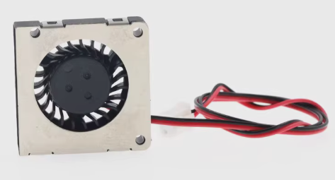
It “catches” air from the front side relative to this picture and blows it out to the left edge. So I’ve installed heatsinks on the ICs and attached fan on the bottom housing plate, slightly before the edge of the WiFi board where it can fin. With the flow out directed towards the installed heatsinks. 30mm side doesn’t covers all 3 completely, but still good at cooling all of them as air get dissipated while hitting the center heatink.
Had to drill a hole in housing for the fan air intake. Used a screwdriver with a conic drill. I’m not good with a “handcrafting skills” so ended up with 1 crack but I don’t care as it’s the bottom part which is not seen anyways and it’s still solid and didn’t lost much of the integrity from that crack. Most likely if drilled slower, and applied less tension it would have turned out more neatly. But as I’ve said - I’m not good at it and I’m just fine with the result. Fan are attached with a M1.4 self-tapping screws straight to the housing.
I’ve reversed direction of the hex stands included with the case, so that the rounded “caps” become a housing “legs”, adding some space below it for air intake. Should probably add some dustguard as well but mine are currently seating in a pretty clean environment so I don’t bother for a while, will add it some days later once I’ll find something suitable.
Had a readings of ~67-68 *C from the WiFi module on the board without casing, i.e. open (at the room temp of ~24*C). Without a load, but all 3 APs running. Same environment and conditions but having it inside the housing and aux fan running gives me ~41-42 *C, which I consider could call a success.
The fan I’ve used are not PWM capable itself. But I’ve added an external MOSFET circuit to allow controlling it. Because at the full speed the sound are pretty noticeable. It’s not that load, but still.
BLDC fans without own PWM pin usually can’t be controlled with PWM, like a fans with a PWM wire (which in fact have similar circuit inside, but it’s wired only to a motor, not the logic part which needs constant DC supply), but keeping a PWM frequency pretty low (< ~1 kHz) still works and allows to control the speed of this fan to a certain degree. I don’t hear any additional noise or vibrations coming from this low freq PWM and the noise from a fan itself becomes nearly unnoticeable at PWM levels < ~50%.
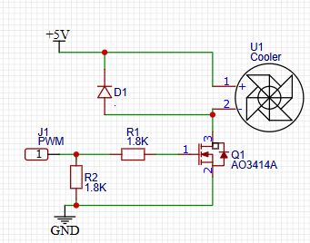
Needs a MOSFET with low Vgs(th) and preferably a low input capacity. I’ve used dmg2302uk I’ve had lying around but something much more common, like AO3414A can be used as well.
I have CPU fan working as well. This one is connected to the +5V, GND and PWM6 pins on the GPIO header (4,6 and 7). I’ve explained how to configure PWM6 (exposed as pin 7 / GPIO62 on the header) just a few comments above in this thread, here: [BPI-R4] CPU fan setup - #102 by NStorm . Both of the fans are working and can be independently PWM-controlled so far.
Also, how the copper heatsinks are holded to the chipsets? Thermal stickers?
Yes, those that I’ve bought had stickers included. I’ve had thermal conductive glue lying around as well, but didn’t used that, just the sticky thing included.
the cpu fan is already connected to the PH-3PIN Connector. can i connect this fan to another connector? i dont care about the PWM i can let it run at full speed
can someone help me out?
It depends on your fan…if it is non-pwm fan you can use gpio header for it using the vcc (3v3/5v depending on your fan) and gnd.
this is the fan: https://www.aliexpress.com/item/1005006620018242.html?spm=a2g0o.order_list.order_list_main.24.66a71802vWMzu9 can someone help me with the GPIO pins i should connect it to?
R4 have a fan connwctor between rj45 and sfp ports,but my tests were not successful with 5v pwm fan because pwm is only max 3v3
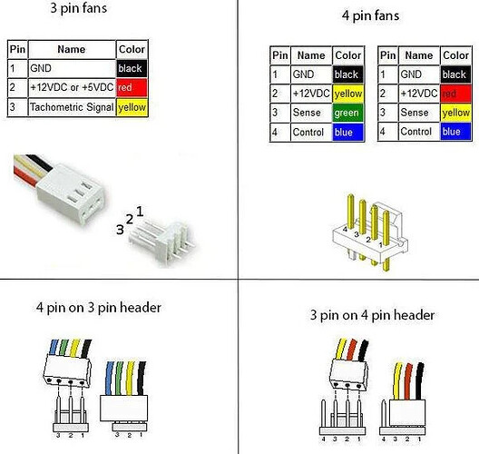
Most fans with a separate PWM-speed-control lead are designed to run at full speed if that lead is left floating. This is a safety measure so that, if the wire comes loose, the system won’t overheat due to the fan stopping.
In general, all fans designed for use in PCs use the same wiring. Starting from the black wire, they are Ground/return, +power (almost always 12V but some non-PC fans use other voltages; check the label on the fan), tachometer (wire is grounded by the fan a certain number of times per revolution, usually 2 or 4) and PWM. The PWM wire is always on the end to allow a 4-wire fan to be plugged into a 3-pin connector for either no speed control or PWM control by interrupting the +power pin.
