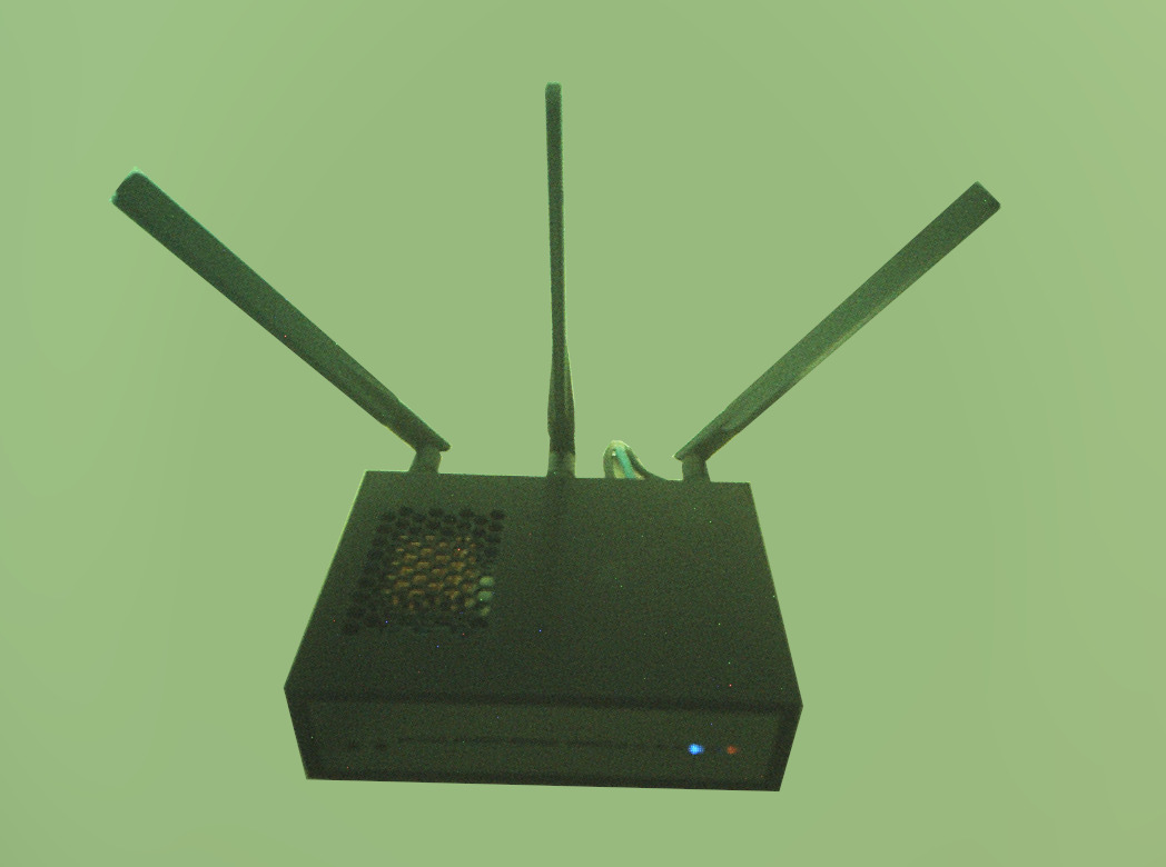
I have remixed this design to allow for a screwless composition (a 6-part modular design + 4 feet) and 3 (wider hole) antennas, the ones sold by AsiaRF in a pack with AW7916. It is meant to mount the board upside-down.
I’m not planning to develop this design any further, just wanted to share it (alongside a source Blender file).
Hi! I was trying to modify the case myself and started with recreating a simplified model of R4 using the CAD files here and dxf drawings from wiki, however the mounting hole spacing is off by 0.5 mm and I have issues getting ports to line up, is this something by design for something effect during 3D printing?
Would it be possible to get the latest version of this in an STL or other format that works well in FreeCad or OpenSCAD? Can’t seem to get the 3mf file to import well to modify.
I created a v2 ceiling access point case. I converted two bpi-r4 to use poe+ and mounted both of them on the ceiling in my home. They’ve been working well with a 120mm fan. I’m seeing idle temps of 33c and peaks of 59c.
Could you maybe upload the latest version of your case in stl again. I like it but have the same problem as the guy before with dividing the parts of 3mf. Since the original metal case creates more RF noise I would switch to a 3D printed case.
I am working on this thing (without any ETA), firstly for myself, because I want something that looks like a standard desktop router from any other brands. A decade ago I had an Archer C7 with very fancy LEDs. I designed something similar by myself and it came out in very good shape from my 3D printer (transparent PLA).
For the technical perspective, for the LEDs, I am using pogo pins, to hijack the ETH LEDs from the connector solder points and three more pogo pins for the reset and WDS button (by this test print, this idea looks like a working one). For the other LEDs (system, storage, internet, wifi1,2,3 and the two SFP LEDs) I defined LED devices on the free GPIOs. Because I wanted to use vanilla, unmodified OpenWRT I had to figure out how to add something for the device tree without touching anything which was provided by the OpenWRT (link). Because my plan is to only use one SIM, this was the only one which has been “extended” to the outer world via some extension cable. I am trying to design it to use as few supports as I can.
It looks great, too. I just wanted something that could be mounted in a 10“ or 19” rack. At the same time, I wanted to address the cooling issue. The fact that there’s no option to mount a fan on top bothers me the most. But since the manufacturers aren’t offering anything, I’ll just have to build something myself…
jens1976, a practical compromise could be a two-piece design: a rack-ear/tray base that holds the board and a separate ventilated top with a 50 mm fan cutout over the CPU. Printing the top face-down avoids most supports, and the fan can pull air across the board and out through side slots. czo, a removable top grille would also let you keep the router-like front while adding cooling later.
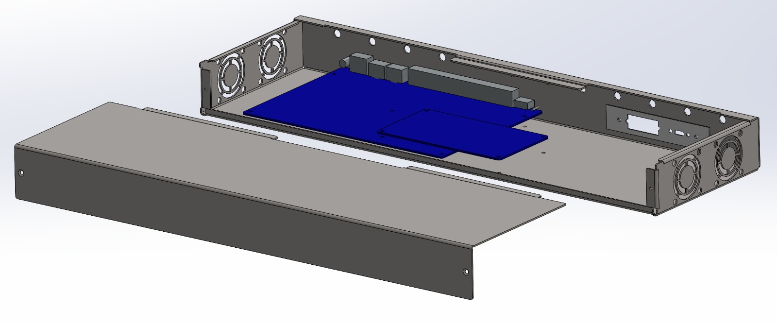
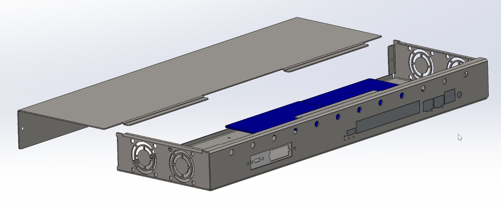
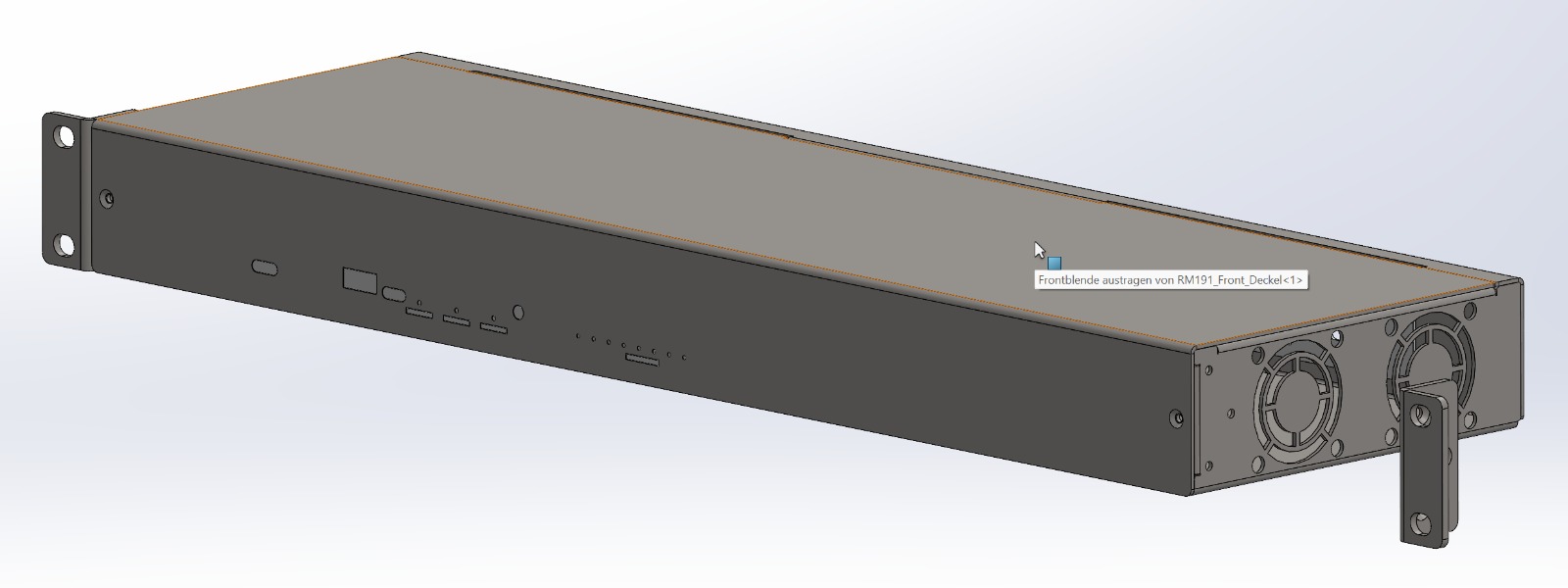
What I showed above was just an idea. I’ve since designed something for the BPI-R4 Pro as well. 1U, full 19“ width. There’s also a version with a cutout for a 2.8” display. That one is 1.5U tall.
The BPI-R4 will probably end up being 1U or 1.5U as well. But then it won’t fit in a 10“ rack anymore. Sure, you could squeeze it in so it fits in a 10” rack, but it would be really tight, and there wouldn’t be any room left for upgrades or other modifications.
I should note, however, that these ideas are not primarily intended for 3D printing, but rather for 1.25 mm metal. However, they can be adapted for 3D printing. I’ve already done some test prints. I think that with the necessary wall thickness, these designs can also be used for 3D printing.