Haven’t seen anything out yet, so made this over the last couple days in some spare time.
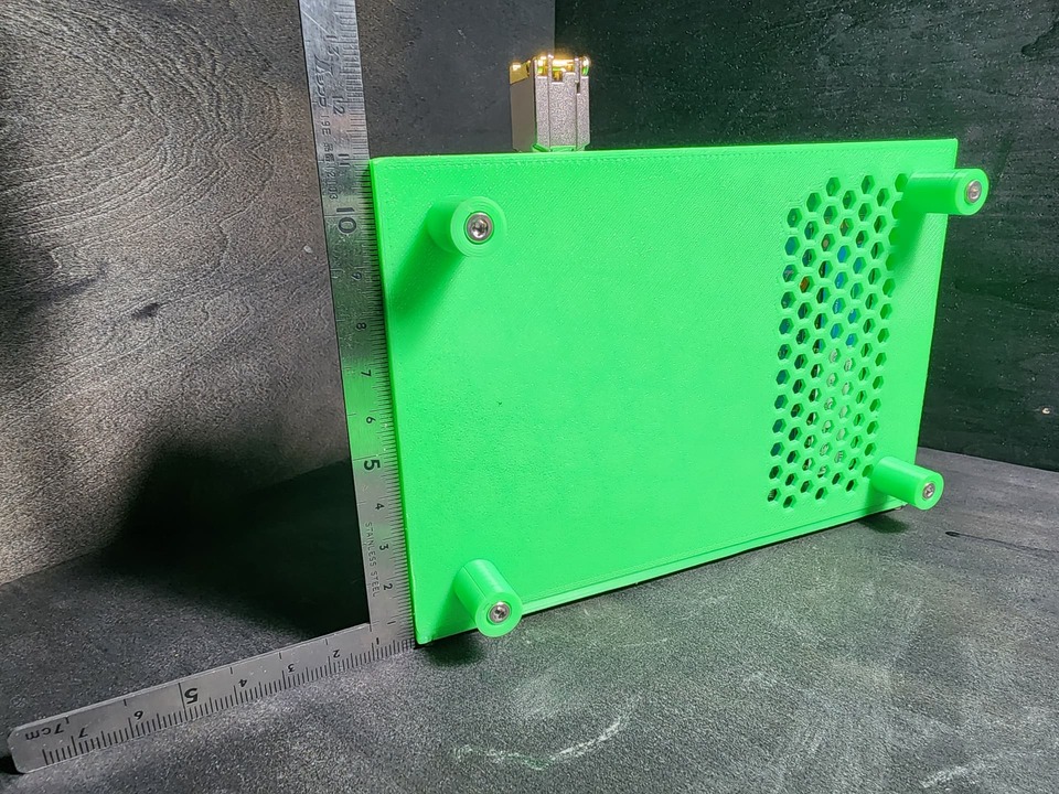
There’s 4 different feet sizes. Pick whichever you want, M3 20/15/12/8mm. It screws into the bottom without the need of a nut.
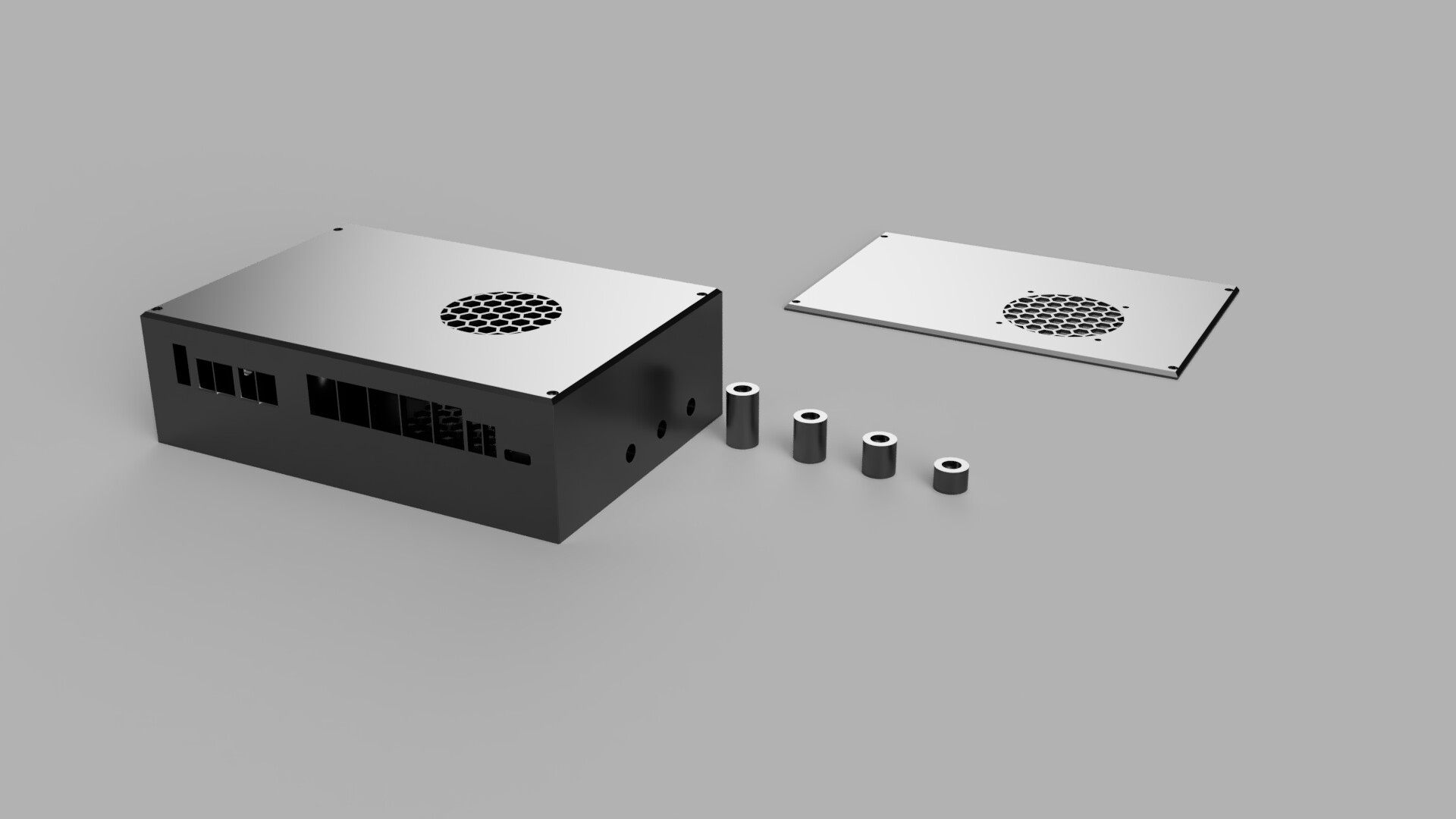
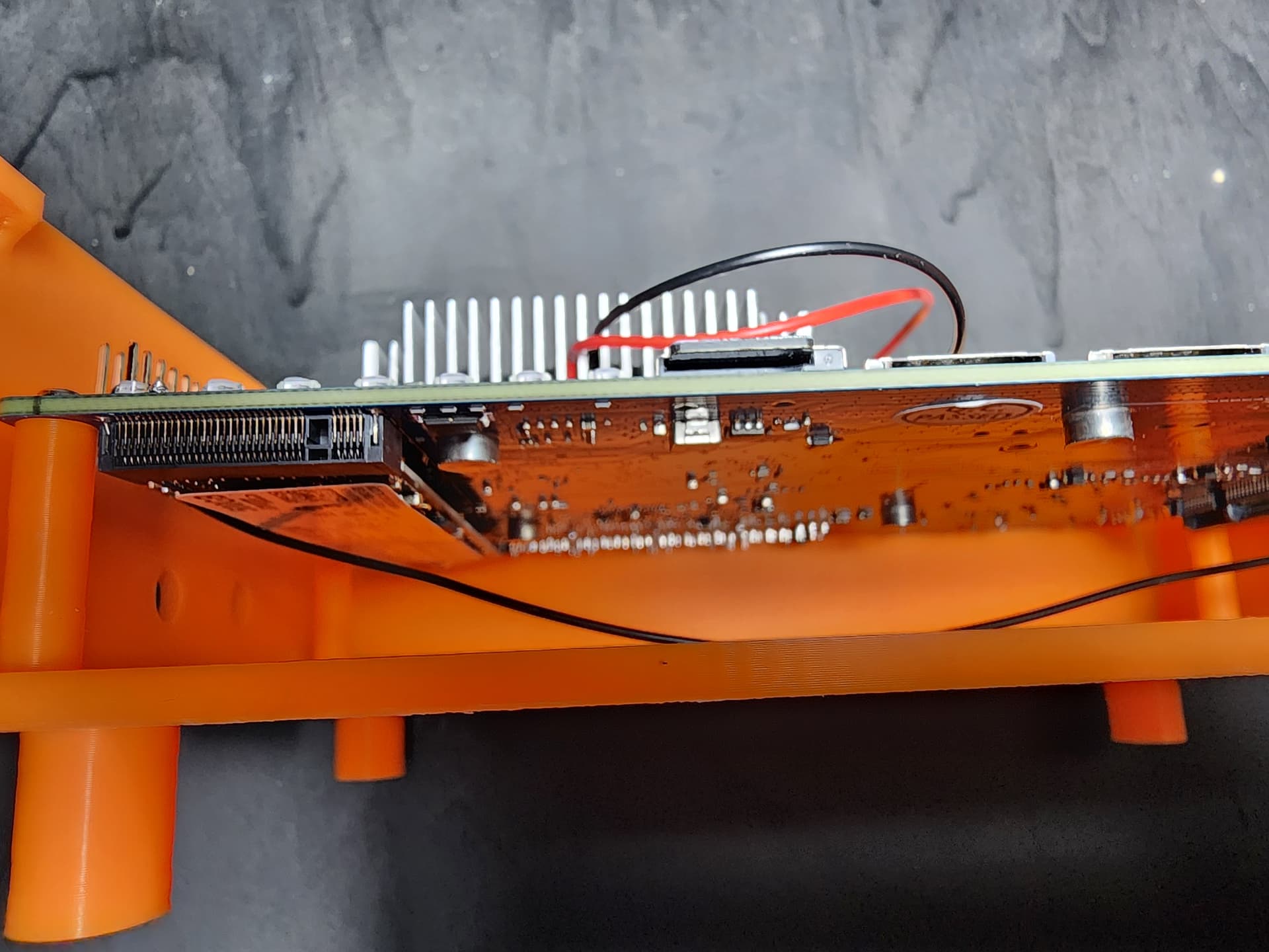
Clearance under the board is ~8mm. Enough for a NVME disk and heatsink on it (if you really want). Case top has two options.
The first one is due to the heatsink I have with a fan built in, forces it to pull in outside air, forcing it around the board, and out the bottom, making it flow over the NVME and wifi card (don’t have one yet).
The second top takes a standard 50mm fan above the CPU.
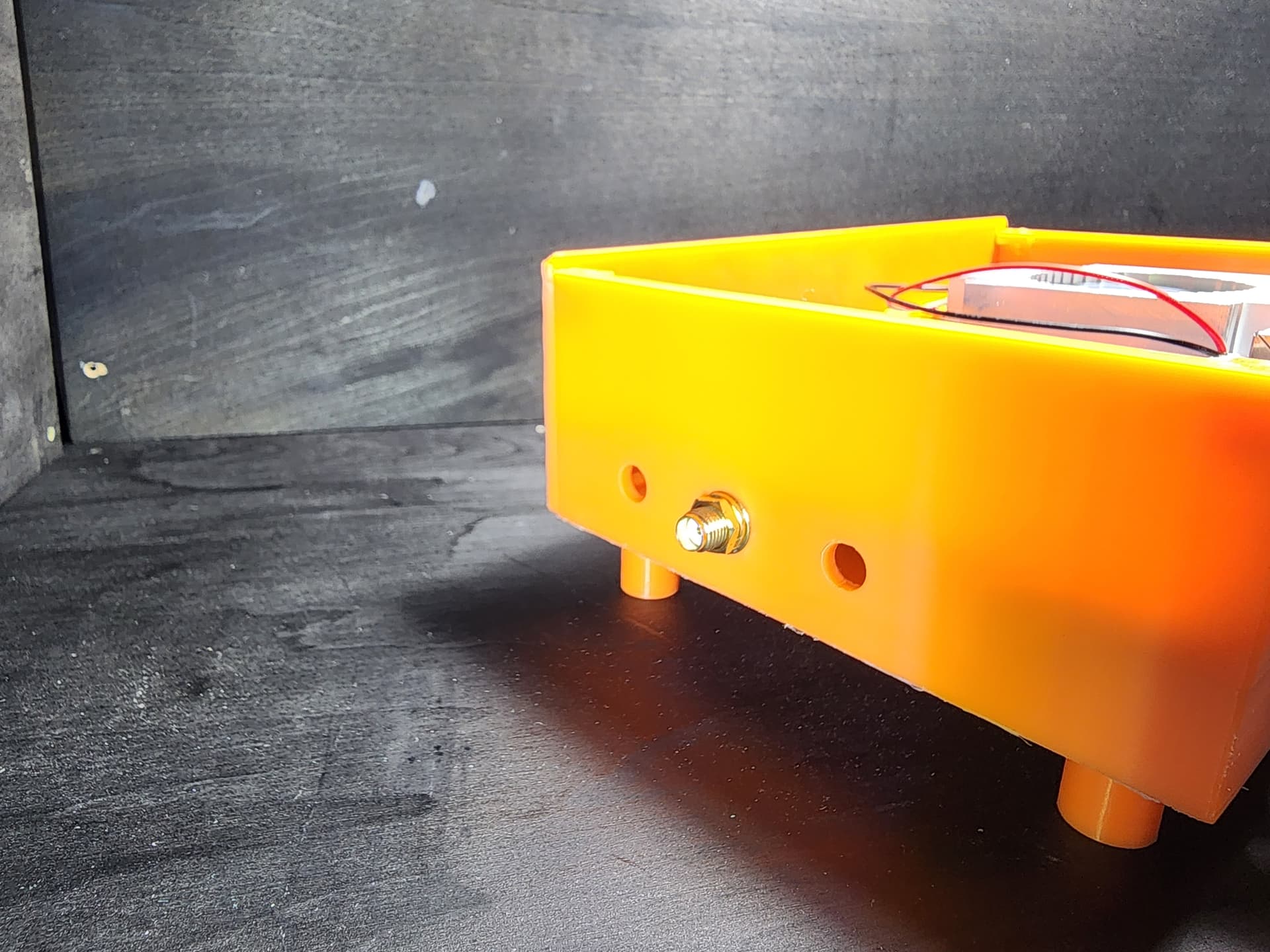
No holes for SMA jacks on the side, because no wifi yet, let alone the number needed (6/7/12/14?)
Back panel and top panel needs M2 bolts (I have a thing for hex wrench bolts), 4 each, 8 total. Size should be between 4 and 8mm. I used 6mm and they work great.
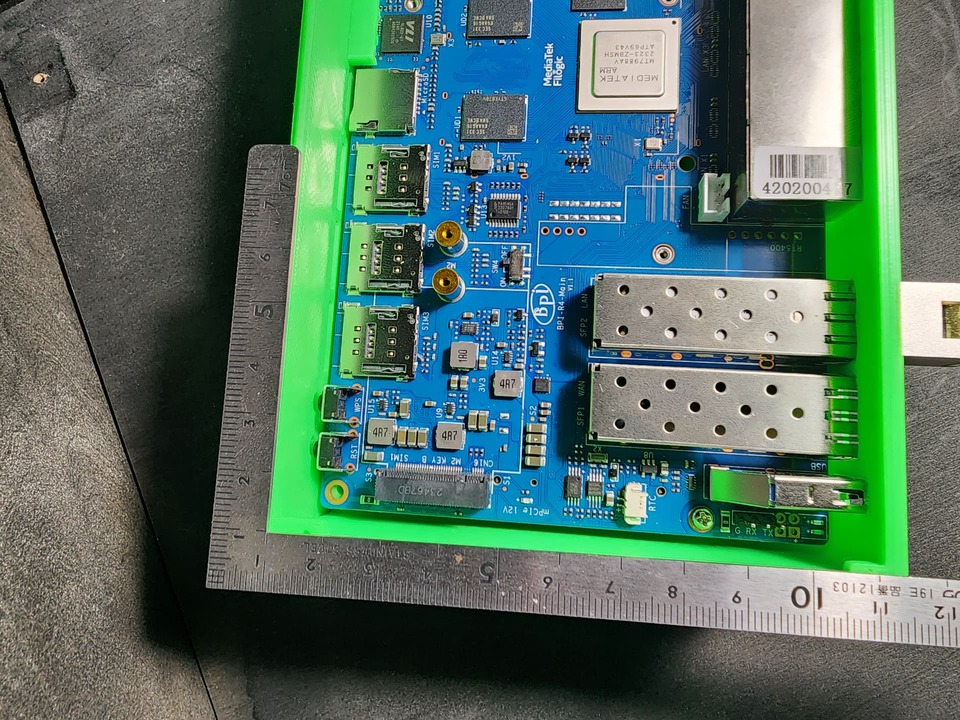
Tolerances on the ports are based on the V11 DXF sheet. Found some things didn’t match, so modified based on the board I have.
Welcome to thoughts or ideas.
Edit:
Updated version if you don’t read the thead. bpi4 case RV1.7.3mf (388.5 KB)
Are you sure M3 is the correct size? Because I measured the holes in the PCB and they are all 3mm wide (as far as accuracy on my ruler goes), which means an M3 screw wouldn’t fit properly.
Instead the better size would be an M2.5, which is also used by raspberry pi and which I also planned on ordering a box of soon.
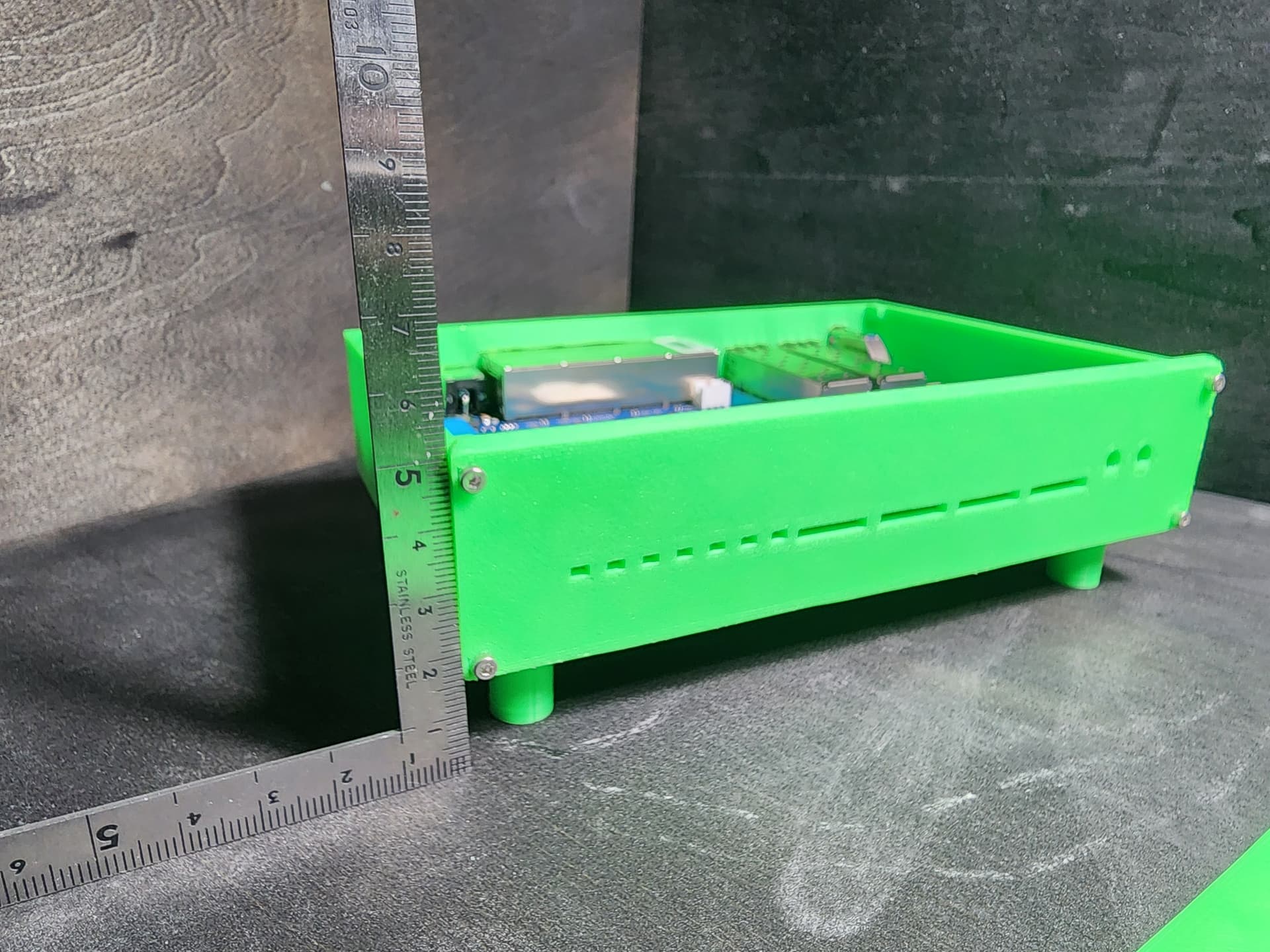
thanks on working on case. can you take pictures on full case? how are the dimensions?
i have wifi-card, it comes with small heatsink, which dimensions do you need? i measured from top of heatsink to upper side of board 13mm, if you need the height. height on top should be at least 20mm from board surface to top cover (inside) to have enough space for debug-uart and wifi-antennas.
i would make 4 holes on left + right (6wifi + 2 for 4g/5g) and if needed later on back there can be more (if 10/14 antenna version comes). more than 4 holes on each side will not be possible to order antennas for wall mount (rj45 to down).
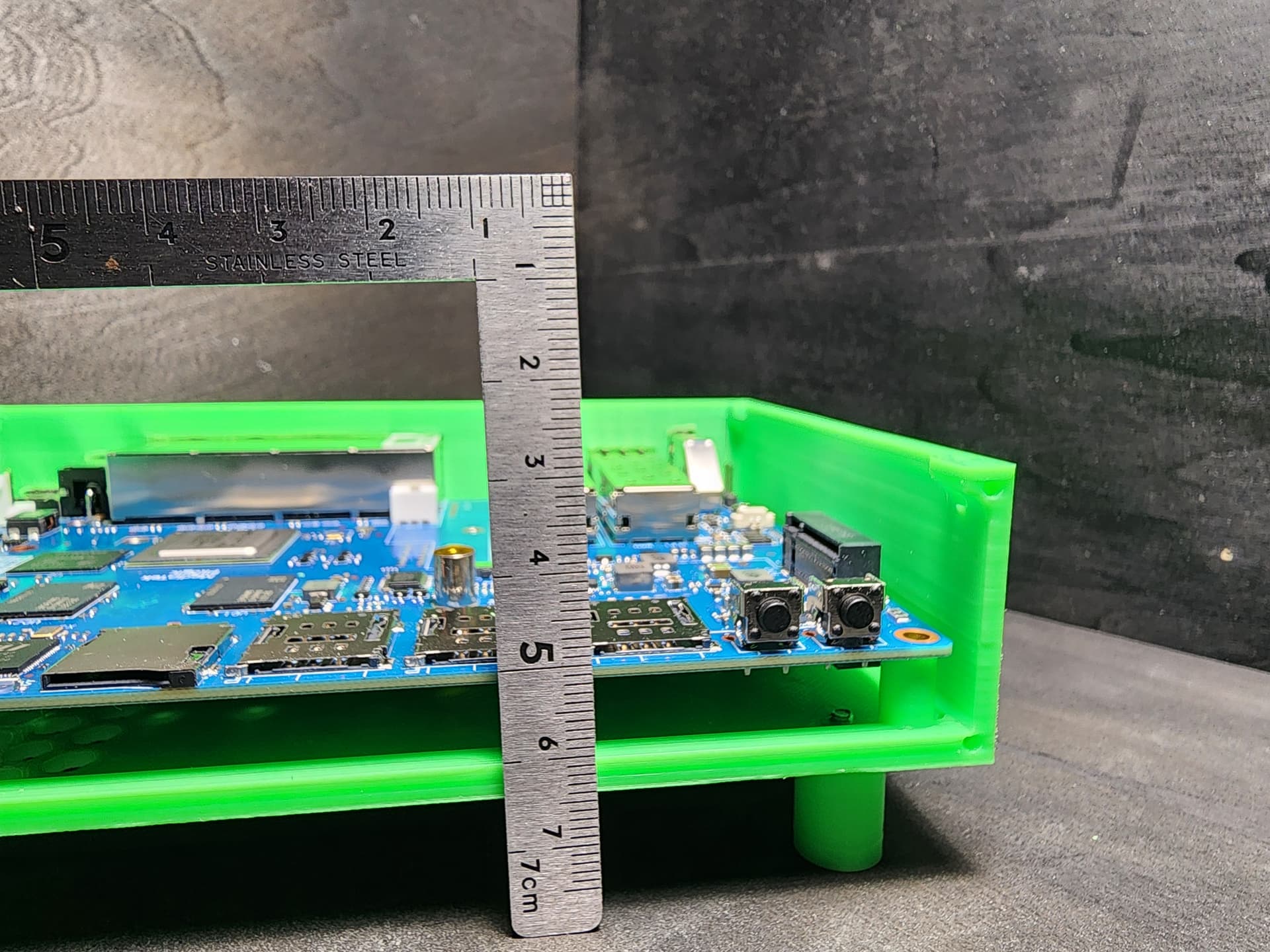
The best volumetric measurements you can get. Photos with a reference would be great too.
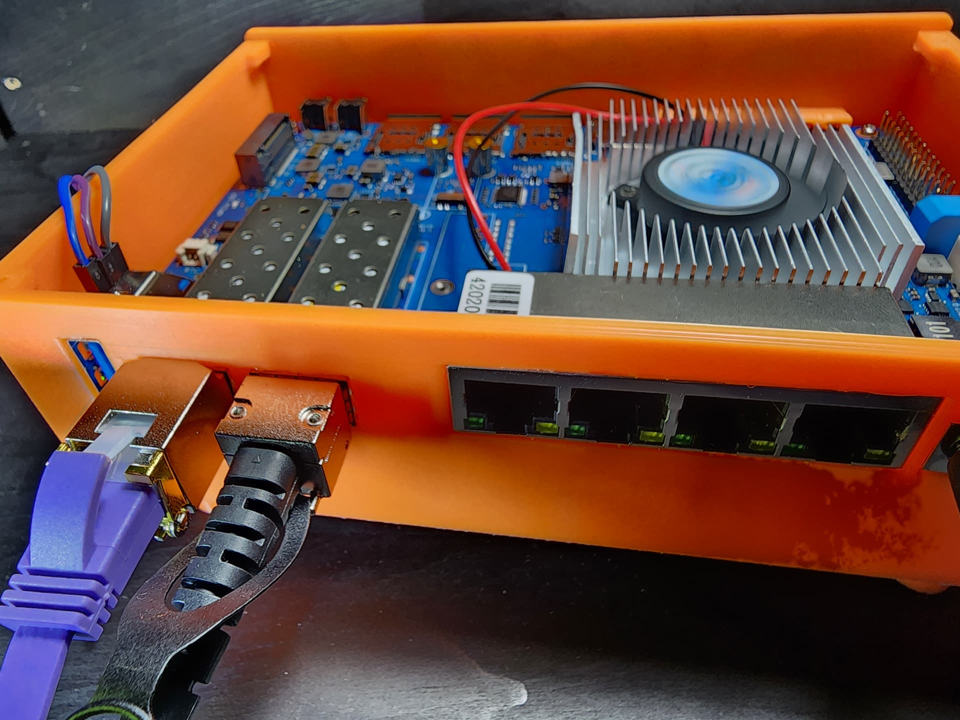
Top of the board to the inside top cover is 22mm at the moment. Wanted to keep heatsink options open and account of any of the connectors.
From the bottom side of the board to the case inside bottom is only 11mm at the moment. Wasn’t sure of the WiFi card and went with a NVME + heatsink, but this can easily be increased.
The SMA connectors have a tight fit (didn’t put in the holes yet remember) under the board, if they are the standard 6mm bulkhead SMA with pigtail.
On the WiFi card, not sure if it’s using IPEX or MMCX. MMCX would need more allowance to reduce bend degrees.
@frank-w I increased the distance under the board to clear the 20mm heat sink I think. Printed it out earlier today and the board slid right into place for me, so everything should be good.
I put the antennas below to make the coax routing easier to the wifi card. I’m not sure how possible it would be to have them above the board and then making the bends without exceeding the radius turn limits for most cables.
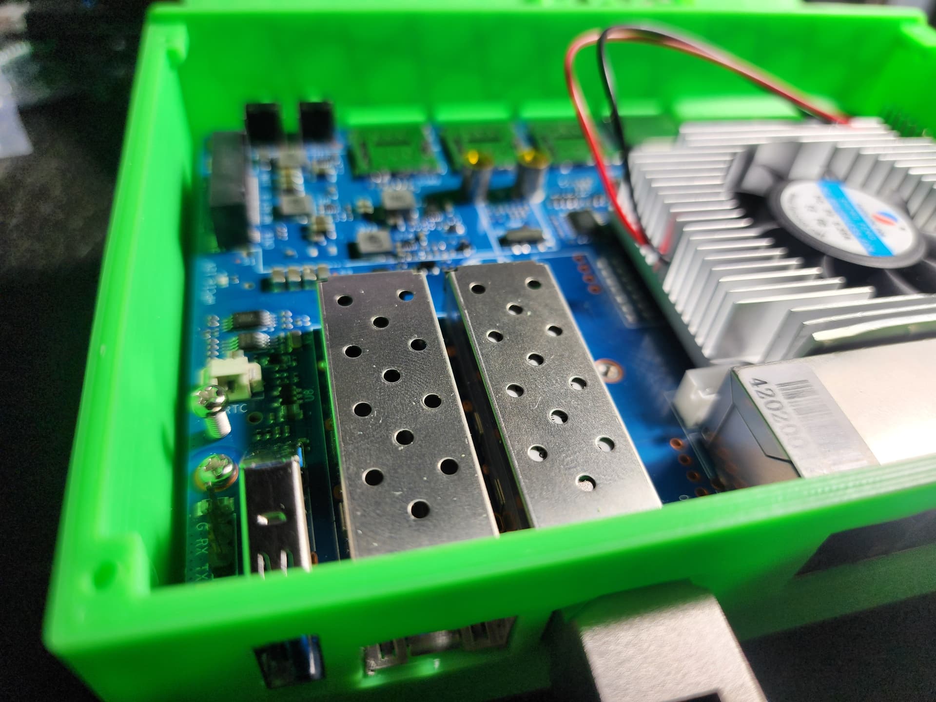
The NVMe isn’t accessible. Could probably make a snap plate or something for that.
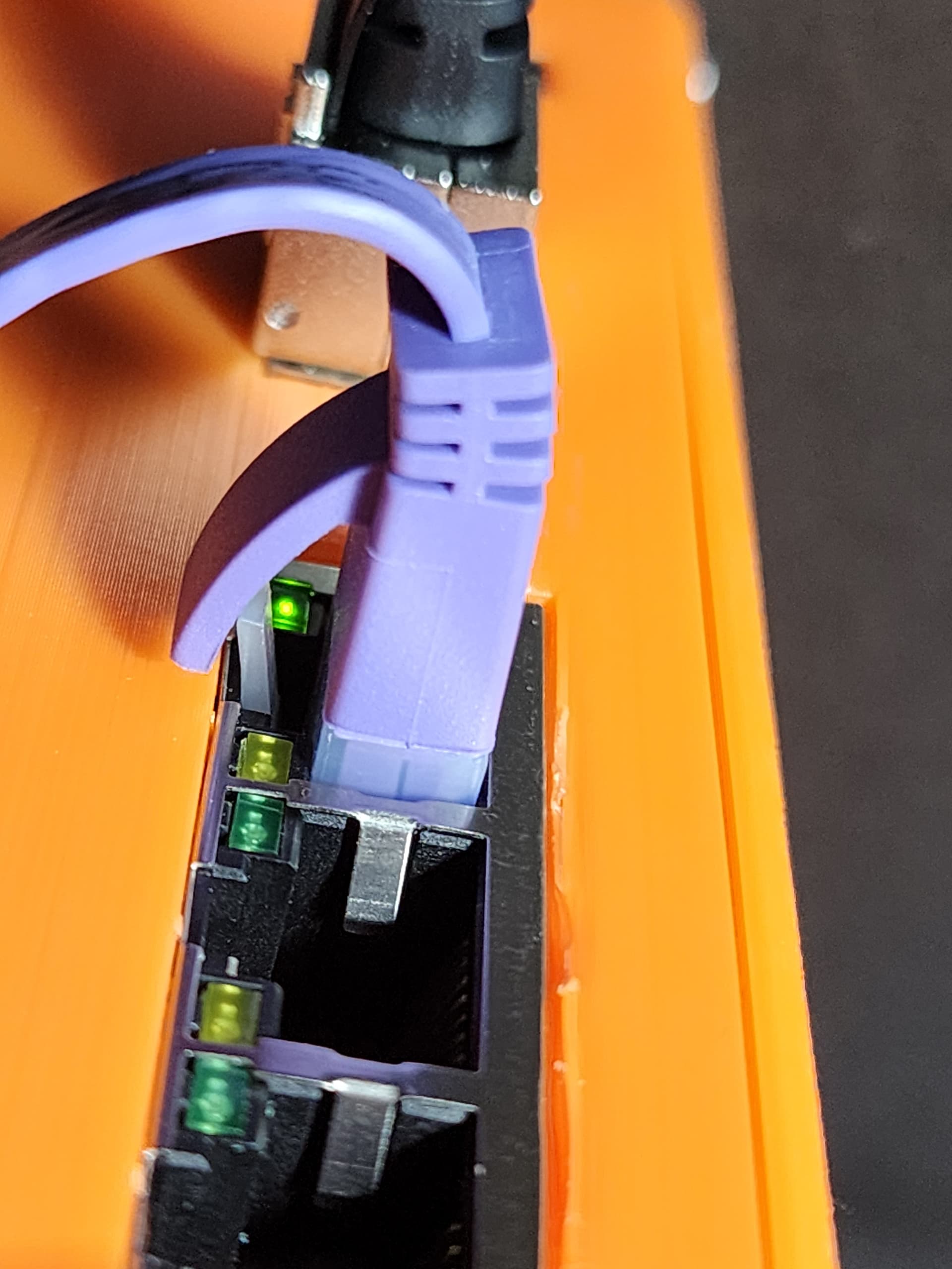
The RJ45’s are actually nearly flush mounted. The clip doesn’t touch the case. The RJ45 block seems to be ~0.25mm offset from the other ports (sfp cages, power), otherwise it would be flush.
Sounds logical…is right/left not enough space for the cables in larger radius? But yes,compared with r3 wifi is on bottom,so it makes sense having antennas also below board.
Ok,then it was a optical illusion in first picture in previous post. Sorry for the noise.
Here’s the STL files. Issue with STL files on something like this, is 3MF each component is still individually unique. So you can include multiple components, see them assembled, but then only print out the objects you need.
About every slicing software should support a 3mf file with preview.
Enough space that you could probably fit several dozen RG174 cables, but I would be more concerned with the bend radius compressing the dielectric core and attenuation. The bulkhead connector I have there is a standard machine produced one, it’s a few cm on the heat-shrink tube.
One possibility would be to go across the top of the board to the opposing side before looping down. This would decrease any bend diameters, but making for some long runs while possibly picking up some weird EMI off the chips and power regulator. (honestly would be interesting on the effects without a RF shield in place)
Ok,then it was a optical illusion in first picture in previous post. Sorry for the noise.
hah, no problem. high contrast material, trying to use my magnifying loop light, and a cell phone for pics, it’s bound to lead to weird pictures.