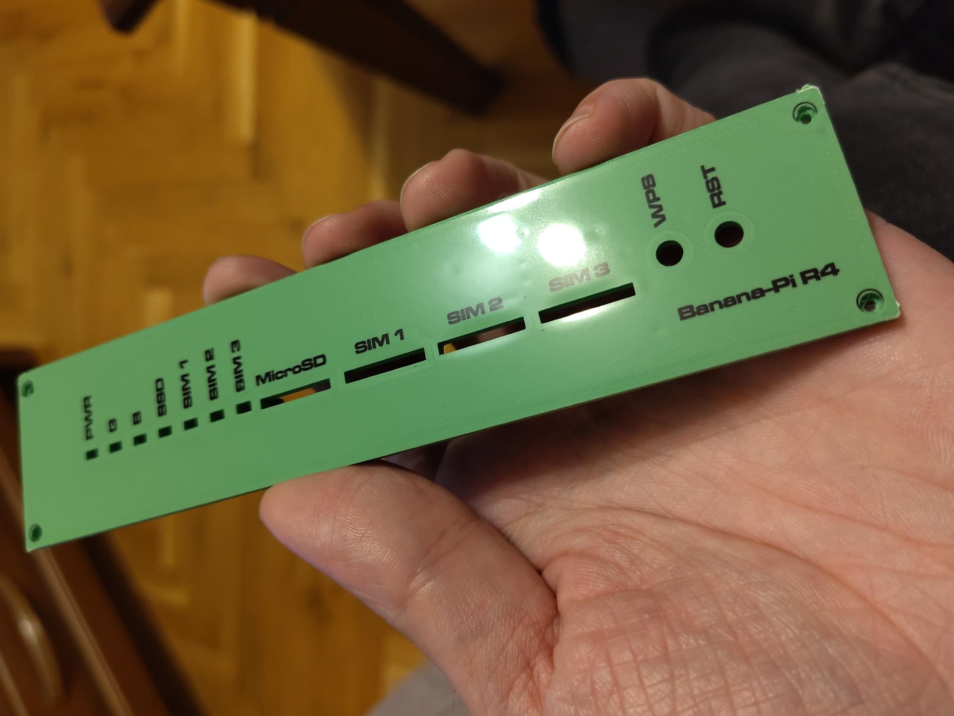
The font I used is Microgramma D Extended. Don’t forget to enable mirrored output and disable scaling when printing on the transparency.
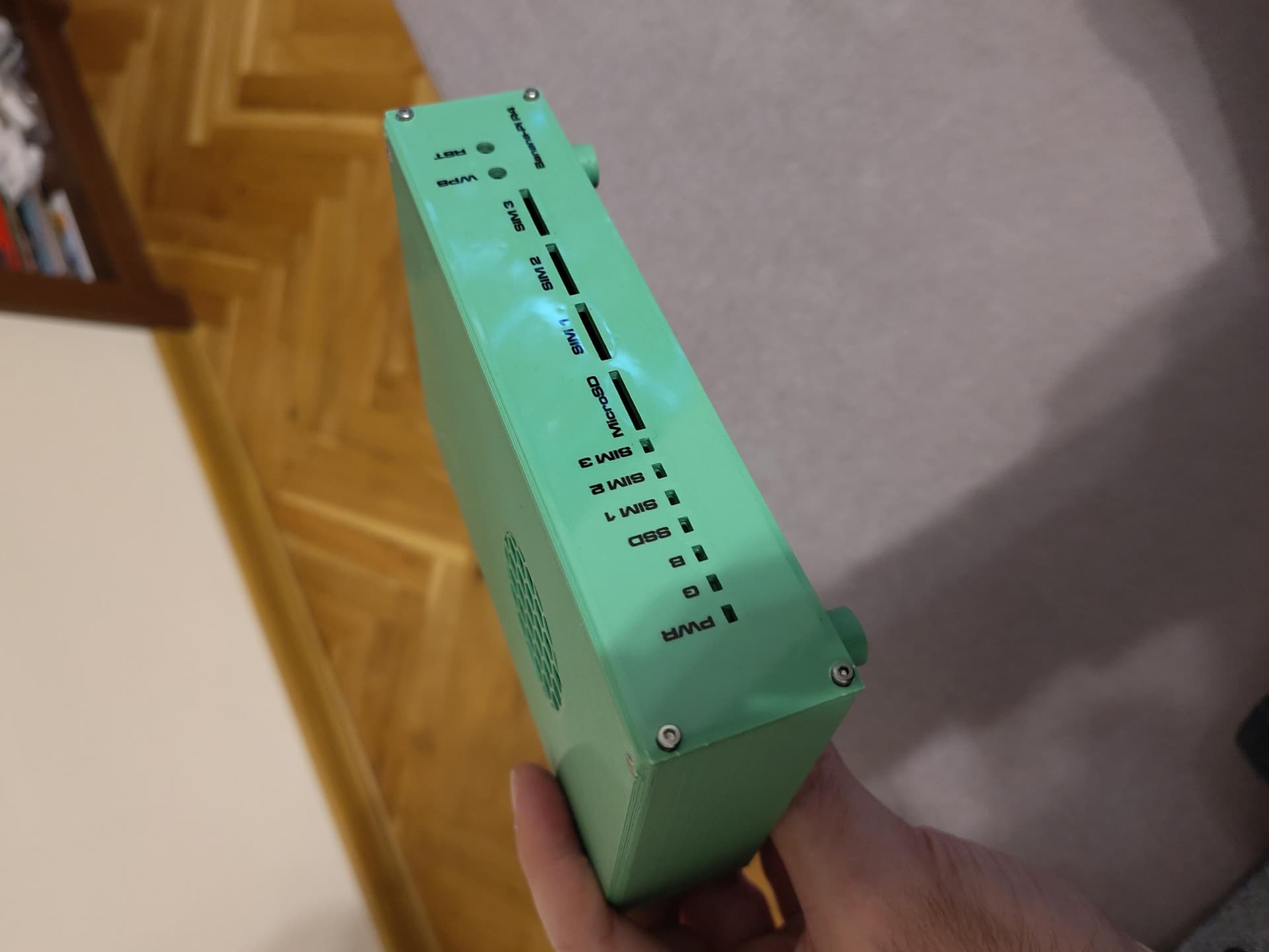
Also important – your bed must be trammed as usual (you should not take into account the additional thickness of the transparency foil). The additional squish of the molten plastic makes the final finish completely smooth and flat (no lines as with the normal 3d printing first layers), and it makes sure the toner gets transferred.
The RJ45 block and the SFP cages should be mounted flush on the board. There’s probably a small deviation, but I had put in the recommended tolerance of 10.20 and 15.15 on them to allow. On the RJ45 block I had added an extra 0.25mm to the sides and 0.40mm to the height to allow for tolerances. (recommended tolerances are not listed in the specs document)
The USB-C plug with the current case should allow for a 0.1mm to 0.2mm clearance on the minimum USB-C size specifications of 6.51mm minimum of exposed shell/gnd. (https://www.usb.org/sites/default/files/USB%20Type-C%20Spec%20R2.0%20-%20August%202019.pdf page 57) You should be able to slide 1~2 sheets of paper between the non-exposed cable shell and the case.
With 3D printing, there are several other factors that start coming into play. Material shrinks, and the nozzle diameter maters. In the slicing software if you have something that’s 2mm thick, its actual thickness will be determined by the line width. Printing something with 0.4 and 0.8 will lead to slight differences. The slicer software can hide some of these facts, so attention needs to be paid in the settings.
Shrinkage of the material will also play a factor. PLA you can expect ~0.5%, ABS and you can start approaching 2%. While it doesn’t sound like a lot, you print something that’s 150mm and it shrinks 2%, it’s going to be 147mm when it cools.
Actually, looking at the original sized pics that you had posted there, there’s something wrong with the mounting of the board or the print.
The SFP cages should be flush with the face, but in the pic it looks like yours are back 1~1.5mm. (PCB setback is 6.875mm)
The RJ45 block should be almost flush, like ~0.15mm at most away from the face (PCB setback is at ~6.74 mm)
The DC jack will also be the same as the RJ45 block, either flush or just slightly recessed. (if I print using a 0.4 nozzle, it’s flush, a 0.6, it’s slightly recessed)
On the inside, the board should be flush against the inside face.
If you don’t have the SFP cages flush with the front, then you won’t actually be able to insert any modules into them because the case will keep them from being able to insert all the way due to the module locks on the bottom. I’m using DAC and 10Gbit modules in mine and they fully insert correctly, locking into place.
Thanks! I just ordered a bpi-r4, barebones. I have to wait a few weeks for shipping. In the meantime, I’m keen to print a case for it. Just leaving a comment here so you know there’s still interest from the masses.
Really nice.
Would you have the files in a format that would be compatible with easy editing in FreeCad ?
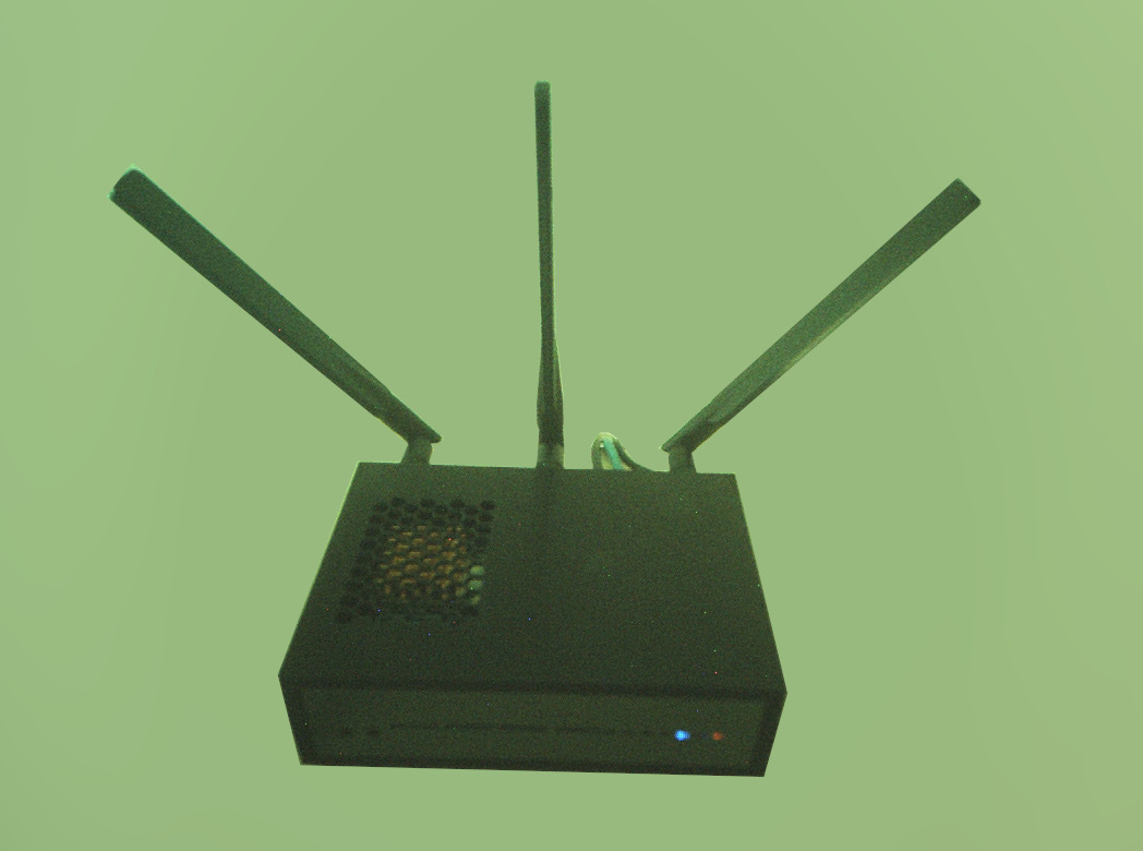
I’ve a 5G modem on the top slot and need 4 holes for the antennas above the PCB.
AsiaRFs’ Paul Lai just responded to my email where he says,
“Kindly be noted the single mini PCIe or M.2 module will be available in next month.” [emphasis added], referring to the Wifi 7 board for the Banana Pi BPI-R4.
I found it a little confusing too as English is their second language. I’ll just post the whole conversation.
I was going to order “Wi-Fi 7 Module AW7256-P01 Mini PCle MediaTek MT7996AV” from AsiaRF which was available on their website a couple days ago. It has since been removed.
Me: “I am looking to buy a wifi 7 module (Wi-Fi 7 Module AW7256-P01 Mini PCle MediaTek MT7996AV) for a Banana Pi-R4 for evaluation and research purposes, but when I added the item to my cart and did checkout, the shipping was calculated to be $138USD. That’s a little crazy. I was wondering if you could give me a better quote for shipping to this address: [Removed]”
Paul Lai: “Dear Radford, Excuse us, we are sorry some issues in our web system. We will be available for customer ordering in next week for full board system. Please order later for full system. We don’t sell module only now. Kindly be noted the single mini PCIe or M.2 module will be available in next month.”
(This should probably be in its own thread anyway. I originally just meant to quickly update following jcdutton’s last comment)
Hello, on the box where the switches for reading from the nand or sd card are, can you make a hole to move the position of the levers without taking the cover apart.
Hi all! I understand that the problem of all engineers and electronics specialists (including me) is the case. I would like to ask: maybe together we can draw something other than a parallelepiped? Something more modern and different looking? At the moment, I asked a friend to draw a body similar or the same as that of the TPlink Be900, but he is still on vacation. Therefore, for now I’ll start sketching, taking into account the fact that the case is supposed to have a removable fan and a 2.5-inch hard drive for files. So, if you are interested, I will post the result here.
I have remixed this design to allow for a screwless composition (a 6-part modular design + 4 feet) and 3 (wider hole) antennas, the ones sold by AsiaRF in a pack with AW7916. It is meant to mount the board upside-down.
I’m not planning to develop this design any further, just wanted to share it (alongside a source Blender file).
Hi! I was trying to modify the case myself and started with recreating a simplified model of R4 using the CAD files here and dxf drawings from wiki, however the mounting hole spacing is off by 0.5 mm and I have issues getting ports to line up, is this something by design for something effect during 3D printing?
Would it be possible to get the latest version of this in an STL or other format that works well in FreeCad or OpenSCAD? Can’t seem to get the 3mf file to import well to modify.
 bpi-r4-labels.pdf (9.1 KB)