How to mount the antenna to the box

Hi,

I have an official R3 box and the antennas… I received the following small things with the antennas: parts

Which thing goes to the inner side of the box, which is outside? In which order and which direction (for the part nr 1.)

I know that this is a very beginner question, and probably does not really matter, since it works without them anyway… but I’d like to know the correct method to mount the antennas.

Another question: Is there a recommended way to mount the 8 antennas? So for example all 2.4 to one side or mixing them on the 2 sides? The labels on the box does not help, since they are WF1… WF8, but on the board they called 2.4 WF0-WF3 and 5 WF0-WF3

Thanks, Gábor

without 1+3 you get rotating force onto your case which is bad, so basicly 1 outside one inside between case and nut. imho outside should be the thinner one (1).

so from ounter to inner:

antenna bolt with 1 (tooths to case), case, 3,2

correct me if i’m wrong

Thank you very much.

Normally I mount it thus:


       | |<----case
 __    | |
   |   | |  
   | { | | |   ]
   |-{-----|---]--\
     {     /   ]  | <-----plug
   |-{-----/---]--/
   | { | | |   ]
 __|   | | 
     1 | | 3   2

#1 (tooth lock washer) prevents the plug from rotating against the case, #2 (nut) pulls the plug tightly against #1, and #3 (split lock washer) prevents #2 from unscrewing by adding a sheer force against it on one side.

Normally, though, the ones I use have external tooth lock washers that will bite both sides.

4 Likes

I’m curious about his second question, what order did you guys use for the antennas?

Ohooo we even get an ASCI Art and mechanically grounded explanation. Nice one.

But the second Question is one that i’ve asked myself as well.

Would it be better to have all 2.4ghz antennas left and 5ghz right? Or mix em Up, one Left one right?

I’ve done a all left, all right configuration and using sinovoip build had huge interference by putting the receiving device behind the other antennas. But using the OpenWRT snapshot build that effect did not happen that strongly anymore.

I asked myself also about antenna configuration. I mixed them 2 by 2. So on each side I have 2 antennas for 2.4 Ghz and 2 for 5GHz. This way I think it is better because devices can be on either side of the board and WiFi is basically a “line of sight”, which means the better the device and the AP see each other, the better the transfer of the data.

This is a very reasonable orientation, and is great for a centrally located router.

Antenna configuration is actually a pretty complex topic. The answer depends very much on your home layout, how many walls and floors you need to penetrate, and on the very complex way in which multiple antennae shape a signal

In general a dipole radiates strongest in a plane 90 degrees from the direction it points (along the broadside of the antenna). Multiple dipoles tend to shape that signal more strongly in the direction 90 degrees from the direction the antennae are lined up (out from the “flat” of the two antennae). This is why truckers often had two CB antennae, one on either side of the cab on its mirrors, as they shaped the signal more strongly ahead and behind the truck. If your signal cables are different lengths, though, this will introduce e a phase change in the antennae that will induce deflection, and is the way phased arrays work. At 5GHz, which is a wavelength of about 5cm, it doesn’t take much difference in cable length to induce a significant phase shift and this will make your signal pattern very resistant to prediction.

My primary router, for ease of installation, is placed at the far end of my house on the second floor. So I placed all four 5GHz antennae on one side and shaped their flats to be more strongly radiating toward the house. I was less concerned about 2.4GHz since it has much better penetration, and found that I got sufficient coverage even with them being on the other side of the router. But I am sacrificing some 2.4GHz signal to improve my 5GHz throughout my house.

If your router is fairly central, then 2 & 2 is a great idea. Just don’t forget your upstairs and basement (if you have any).

I apologize if that’s more than people want to know. I’m an amateur radio enthusiast, and you caught me astride my hobby horse. :wink:

1 Like

Well, this is getting into good discussion. Without getting into too much details, have you tried different kind of antennas with this board? The box seems to come with 5dBI antennas, which seems to be fine for general usage, but what about more powerfull ones - say 10dBI?

I did try 2 + 2 and and one side only config.

Speed did not differ… the beamforming seems to be sort of black magic, either it works or not.

General rule tho, antenas has to be same. It tried to mix different gain ones just for fun and it tanked 5Ghz speed.

Would not be so hasty calling those Aliexpress antenas 5dBi especially those 10dBi ones… 3dBi+

First, remember that about 99% of the antennae that say they are 5dBi gain are really just dipoles that have an actual gain of 2.14dBi. So don’t be too trusting of those dB gain numbers you see.

Next remember that “gain” in an antenna isn’t actual gain in the sense you get from an amplifier. It’s shaping/sensitivity in a particular direction at the expense of loss in another. The “i” means isotropic, which is a theoretical antenna that is a perfectly omnidirectional radiator. 5dBi means in one direction or plane the antenna radiates more strongly by 5dB, and in other areas it radiates 5dB weaker. Here is the radiation pattern of a standard dipole, looking at it from the side. Don’t look at the ring numbers, the outer ring is actually set to 2.14dBi, which is the actual gain of a dipole.

dipolepattern

You will naturally get more than the normal 2.14dBi dipole “gain” just because you have more than one dipole. As I mentioned, two dipoles tend to focus the signal not just in the squished plane of a single dipole, but also linearly (like the CB radios example).

To get 10dBi you need something really special. A colinear array is a special kind of dipole - really a bunch of dipoles linearly arranged one atop the other. Each one that you stack more strongly focuses the signal in the plane of the antenna (at the expense of signal going up and down). To get 10dBi from one you’d need enough elements that the entire antenna would be 1m long. The only other 10dBi method would be a directional horn.

My advice is to use normal dipoles and if there is extra shaping you want to do, arrange the antennae in such a way as their mutual emission pattern shapes the signal.

2 Likes

can you give more details here? which kind of antennas do you suggest here (round/flat, short/long,3/5/8/… dbi)? and how to arrange them? @finas posted a 3d case model which has 4 left and 4 right, should we make 2g4 on one side and 5g on the other to have less interference or is mixing better as they operate on different base-band and so no interference happens?

I assumed something like that… if not there would already be a “known best possition”. Glad to have a professional around that is willing to answer questions. Thanks :slight_smile:

I think im might need some more imagtinative assistance on this topic.

Having one Antenna will radiate 90° outwards. In a circle all around right?

image

Now if we have 4 antennas in a Line, which one would be the “flat” side? Tried to paint that from a TopDown view: Something like that? image

P.S i only have to cover one floor so no need for a certain angle. Jus keep em all straight Up, correct?

Who can answer me some questions about antennas for BPI-R3 via PM (I want to buy some antennas, but will they connect to router?)? I don’t want to post this question publicly, because I don’t want to advertise these antennas.

I’ll try to answer questions, but keep in mind this is really complex. Radiation patterns depend on antenna placement, shape, and gain, but also on channel settings. MIMO, for example, complicates things a lot.

Simple questions first:

Correct!

Yes, thats correct. If they are all operating together it will shape the signal like that. MIMO tends to make them operate in individual lobes like I showed above, but overall still in the shape you show.

I’d likely rabbit-ear them a little, just to help the signal spread around objects, and to help with polarization.

A dipole puts out a signal polarized in the direction it points. Like polarized light. The antennae in devices tend not to be dipoles - they try and make them fairly omnidirectional, but that’s not possible in all instances (and given the flatness of phones and tablets). So if you have 100% vertical polarization in your router, but your device has an antenna that is more sensitive to a signal with horizontal polarization, then even given good signal strength you’ll lose signal. So rabbit ear them a little, or maybe lay one down, just to mix up the polarization in your footprint.

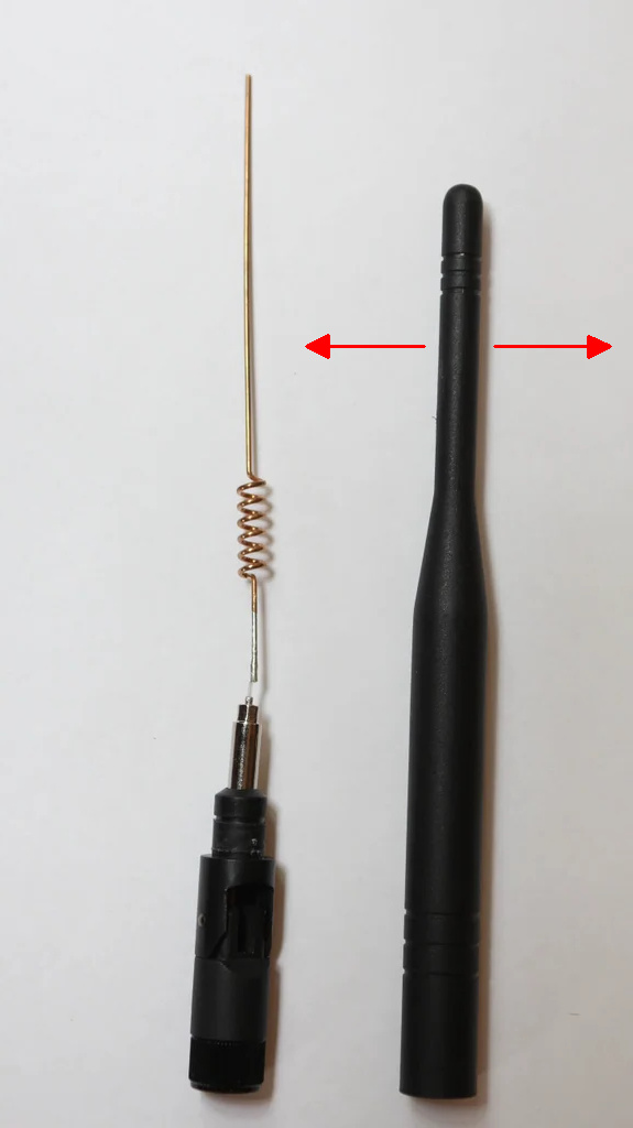
Most antenna that are round vs flat but which are still long are usually dipoles inside a plastic molding made to look cool. It’s possible that they have some sort of etched PCB antenna inside, in which case the signal pattern is anyone’s guess (depends on the shape of the trace), but more often than not when you break them open they are just a dipole.

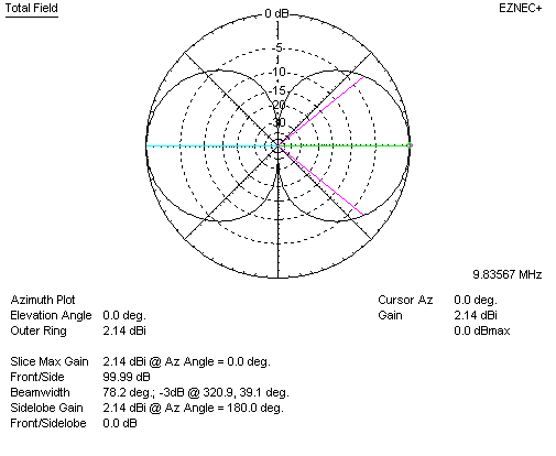
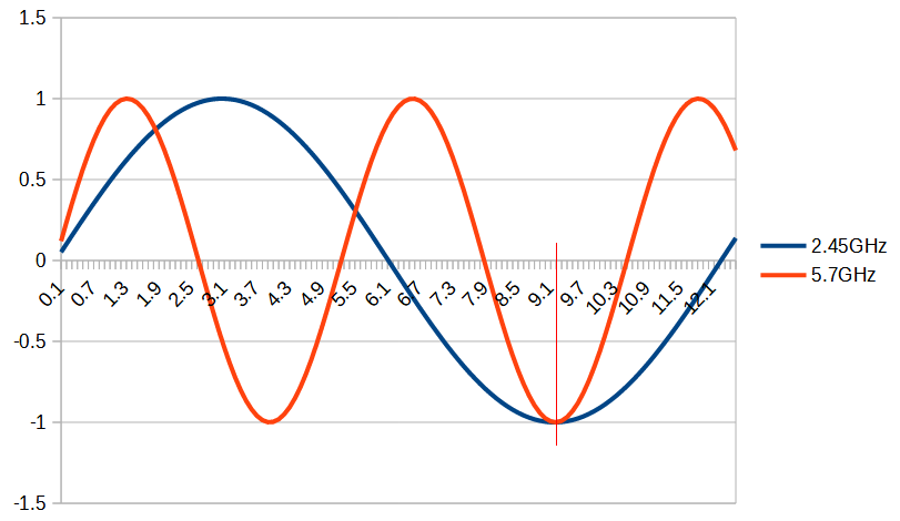
For gain, as mentioned, MOST of the gain numbers in ads on Ali Express or even Amazon are fairy tales. A dipole gives 2.14dBi gain. A thee element colinear might give 5 or 6dBi gain but will be 40cm long. To get the 8-12dBi gain claimed by some, you’d need a colinear antenna that’s a good 1m long. These exist, but aren’t really practical.

The gain of those antenna shapes the signal to be more and more like a frisbee (a dipole is like a donut), flattening it out. Maybe good for single-floor, but very strongly polarized, and harder to make efficient and broadband.

I tend to stick with normal dipoles.

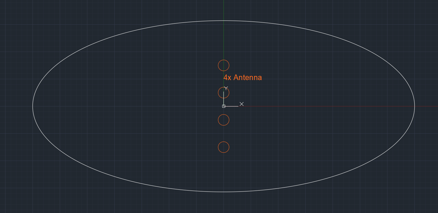
For a centrally located router on a single-floor dwelling, with a 4+4 antenna placement on the case, I would recommend dipole antennae with the 5GHz placed in the corners and 2.4GHz placed in the middle on either side:

5g    5g
2g4  2g4
2g4  2g4
5g    5g

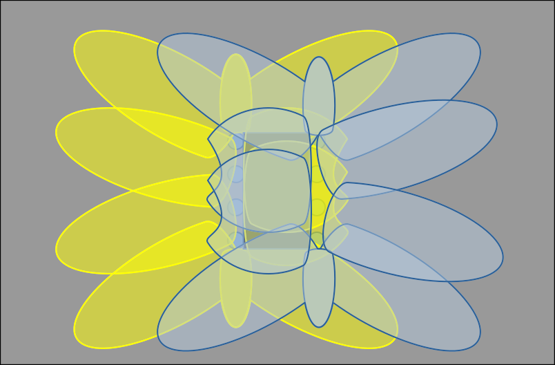
Even when they are not broadcasting together or on the same frequency, the physical placement of the other antennae will still shape the signal. In a 4+4 arrangement, you can expect each antenna to produce primary lobes that look something like this:

Lobes Lobes2

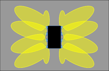
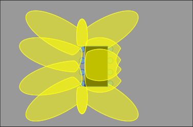
The first diagram shows the pattern coming out from the left and right antennae, and for clutter I omitted the signal coming the other way… The second diagram is showing the approximate signal pattern in both directions from the left antennae. These are both significant oversimplifications, and are based on all antenna being straight up. You can, for example, improve the right-hand radiation pattern of the left antennae by laying the top or bottom one down. So if you had 5g on one side and 2.4 on the other, I would likely lay the top antenna on the left side down and the bottom antenna on the right side down.

But for a centrally located router on a single floor dwelling, 5G in the corners and 2.4G in the middle will likely give the best general coverage.

EDIT: Here’s a better diagram. Yellow is signal from left, blue is signal from right. Lobes3

6 Likes

Have you ever measured the real resonant frequency of those china aliexpress antennas? I kinda fail to believe they are able to cut them each at the same length :D.

5.15 GHz to 5.85 GHz imho is a wide range, or it still lands within a margin of error land?

I don’t have equipment (yet) to test at 5GHz, so no. I do occasionally pull one apart and measure it’s length, end loading reactance, etc.

5GHz is a tough band band to match. There are some tricks to widening an antenna’s bandwidth (certain types of reactive loading, antenna thickness, etc), but you’re right, that’s a really wide band.

There is a convenient match between the bands:

image

The marked point (at about 9.2cm) is a 50Ω impedance convergence between an end-fed 1¾ wavelength (at 2.45GHz - about center of the 2g4 band) antenna and an end-fed ¾ wavelength (at 5.7GHz - about channel 144) antenna. So a 2.4GHz/5.7GHz can share the same antenna length. You can tweak those center frequencies some, either by making it not a 50Ω insertion point (and using some form of reactance to balance) or by, say, coming in a little low on the 2g4 band to lower the center frequency on the 5g band. The upper channels on the 5g band tend to be more popular, though, so most dual-band antennae will center the 5g band at about that point. Which is why I try to pick the upper channels if they are free enough.

1 Like

Hi,

This topic/post is very interesting, thanks for all the informations…

I want to ask how you would do if you also have a lte modem with at least a min of one more antenna (i take two, gps is not needed, so no antenna for this).

So my question is, can i take two from the eight antennas or should i drill two more holes into the case for two more antennas?

I planned to use the antennas like this: (from back to front)

5g - 5g

2g - 2g

4g - 4g

5g - 5g

Why i would choose more 5g than 2g? Cause 5G has improved throughput, but less signal distance.

Another idea would be to drill two more holes and make it something like

5g - 5g

2g - 2g

2g - 2g

5g - 5g

4g - 4g

Of course theoretically the second solution should get better signals, but i want know if the first solution could be enough. And for second solution would you drill two holes on the top or also on the side? Any experiences? :smiley:

Hi,

There is an interesting discussion on antenna placement on the BPI-R3 case. My understanding is that MIMO works best if the antennas on the same frequencies are less than 1 wavelength apart from each other. It is best that antennas on different frequencies are more that 3 wavelengths apart.