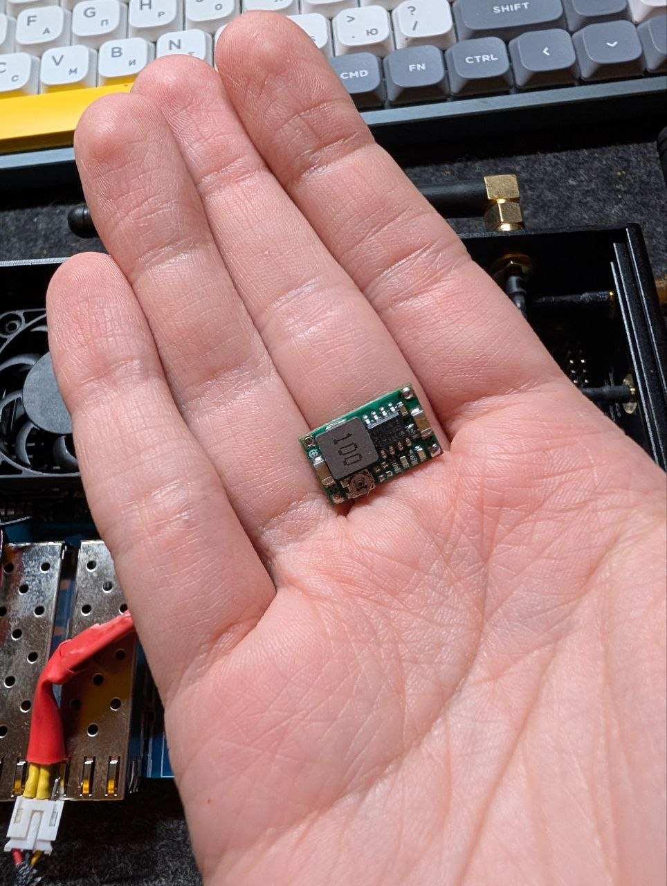
You can temporary override values from devicetree like this: https://wiki.fw-web.de/doku.php?id=en:bpi-r4:start#testing_fan
In my case I need to add new thermal zone. No device tree node exists so far, so it’s not exported to the sysfs interface.
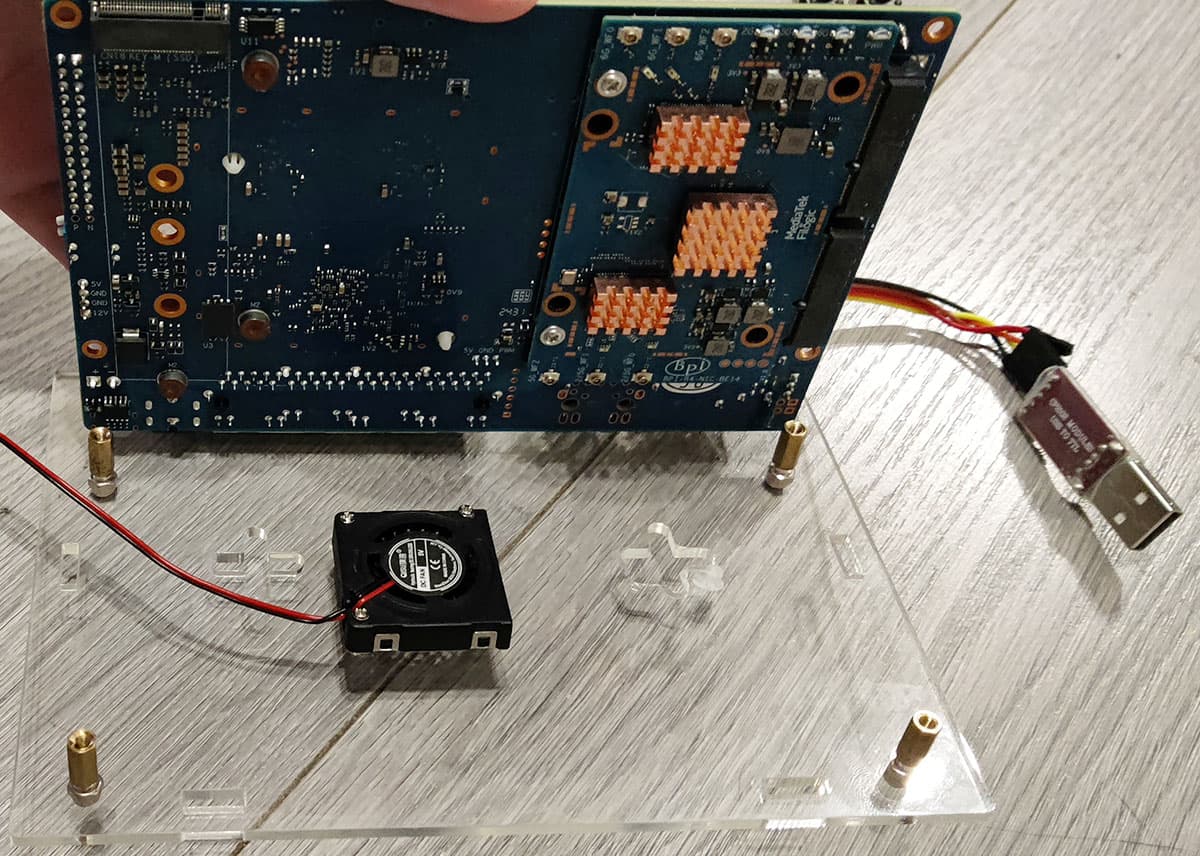
I’ve modded my BPI-R4 to add a secondary fan for WiFi module cooling. Connected PWM signal to the PWM6 channel exposed on the GPIO header. Works good so far if I manually setup pinmux/PWM, as I’ve noted above. Can control it that way via user-space daemon, but would prefer to have kernel hwmon module to manage it. Straight approach is to add required nodes to the device tree, but I’m looking for a way to be able to stick with vanilla OpenWrt kernel/images. Maybe there is a way to add a kernel device tree overlay outside of the FDT image? Or create a new nodes from running OS, or maybe add a new hwmon/thermal zones, not included in the booted device tree.
PS: @frank-w, I’ve noticed you’ve linked my post from your wiki. Feel free to use/copy/modify information from my post, if you would like to include it on your website “inline”, not as a link. No credits/link/etc necessary. You have valuable information there, thanks for your research and sharing!
how did you managed to add a second fan to the wifi module ? what kind of enclosure you are using?
would you mind to take a pic ? thx
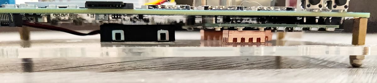
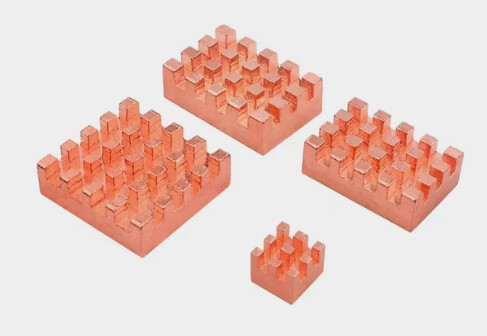
When I was ordering my BPI-R4, I wasn’t sure if the official metal case would be good. Read some rumors that it might be have issues with cooling due to a tight spacing and lacking a design for cooling the bottom part with WiFi board. So I’ve decided to start with a cheap acrylic case I got for ~$3. Turns out it was an option because it seems to have slightly more spacing on the bottom between the board and I could fit 7mm height fan. But not right under the wifi board, where only ~5.5-6mm spacing remains. There are tiny coolers as low as ~3mm available, but they are pretty small in other dimensions, so I did it the other way. I’ve ordered a copper heatsinks for Orange Pi 5, which are ~5mm, and 3 out of 4 in the pack sold have dimensions almost matching dimensions of the chipset ICs. Somewhere around $3 again with shipping.
And ordered a 3007 (30x30x7mm) blower fan, with side-out flow again for the $3.
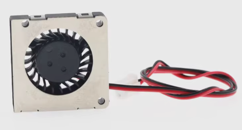
It “catches” air from the front side relative to this picture and blows it out to the left edge. So I’ve installed heatsinks on the ICs and attached fan on the bottom housing plate, slightly before the edge of the WiFi board where it can fin. With the flow out directed towards the installed heatsinks. 30mm side doesn’t covers all 3 completely, but still good at cooling all of them as air get dissipated while hitting the center heatink.
Had to drill a hole in housing for the fan air intake. Used a screwdriver with a conic drill. I’m not good with a “handcrafting skills” so ended up with 1 crack but I don’t care as it’s the bottom part which is not seen anyways and it’s still solid and didn’t lost much of the integrity from that crack. Most likely if drilled slower, and applied less tension it would have turned out more neatly. But as I’ve said - I’m not good at it and I’m just fine with the result. Fan are attached with a M1.4 self-tapping screws straight to the housing.
I’ve reversed direction of the hex stands included with the case, so that the rounded “caps” become a housing “legs”, adding some space below it for air intake. Should probably add some dustguard as well but mine are currently seating in a pretty clean environment so I don’t bother for a while, will add it some days later once I’ll find something suitable.
Had a readings of ~67-68 *C from the WiFi module on the board without casing, i.e. open (at the room temp of ~24*C). Without a load, but all 3 APs running. Same environment and conditions but having it inside the housing and aux fan running gives me ~41-42 *C, which I consider could call a success.
The fan I’ve used are not PWM capable itself. But I’ve added an external MOSFET circuit to allow controlling it. Because at the full speed the sound are pretty noticeable. It’s not that load, but still.
BLDC fans without own PWM pin usually can’t be controlled with PWM, like a fans with a PWM wire (which in fact have similar circuit inside, but it’s wired only to a motor, not the logic part which needs constant DC supply), but keeping a PWM frequency pretty low (< ~1 kHz) still works and allows to control the speed of this fan to a certain degree. I don’t hear any additional noise or vibrations coming from this low freq PWM and the noise from a fan itself becomes nearly unnoticeable at PWM levels < ~50%.
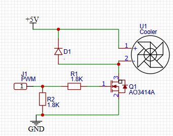
Needs a MOSFET with low Vgs(th) and preferably a low input capacity. I’ve used dmg2302uk I’ve had lying around but something much more common, like AO3414A can be used as well.
I have CPU fan working as well. This one is connected to the +5V, GND and PWM6 pins on the GPIO header (4,6 and 7). I’ve explained how to configure PWM6 (exposed as pin 7 / GPIO62 on the header) just a few comments above in this thread, here: [BPI-R4] CPU fan setup - #102 by NStorm . Both of the fans are working and can be independently PWM-controlled so far.
Also, how the copper heatsinks are holded to the chipsets? Thermal stickers?
Yes, those that I’ve bought had stickers included. I’ve had thermal conductive glue lying around as well, but didn’t used that, just the sticky thing included.
the cpu fan is already connected to the PH-3PIN Connector. can i connect this fan to another connector? i dont care about the PWM i can let it run at full speed
can someone help me out?
It depends on your fan…if it is non-pwm fan you can use gpio header for it using the vcc (3v3/5v depending on your fan) and gnd.
this is the fan: https://www.aliexpress.com/item/1005006620018242.html?spm=a2g0o.order_list.order_list_main.24.66a71802vWMzu9 can someone help me with the GPIO pins i should connect it to?
R4 have a fan connwctor between rj45 and sfp ports,but my tests were not successful with 5v pwm fan because pwm is only max 3v3
Most fans with a separate PWM-speed-control lead are designed to run at full speed if that lead is left floating. This is a safety measure so that, if the wire comes loose, the system won’t overheat due to the fan stopping.
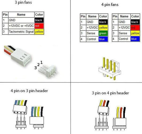
In general, all fans designed for use in PCs use the same wiring. Starting from the black wire, they are Ground/return, +power (almost always 12V but some non-PC fans use other voltages; check the label on the fan), tachometer (wire is grounded by the fan a certain number of times per revolution, usually 2 or 4) and PWM. The PWM wire is always on the end to allow a 4-wire fan to be plugged into a 3-pin connector for either no speed control or PWM control by interrupting the +power pin.
BPI-R4 Fan Control Script
- Operating Environment
OpenWrt: 24.10.2
Script
- pwmfan
# /etc/init.d/pwmfan
cat <<'EOF' > /etc/init.d/pwmfan
#!/bin/sh /etc/rc.common
START=99
PIDFILE=/var/run/pwmfan.pid
start() {
if [ -f $PIDFILE ]; then
PID=$(cat $PIDFILE 2>/dev/null)
if [ -n "$PID" ] && kill -0 "$PID" 2>/dev/null; then
echo "Already running"
return 1
else
rm -f $PIDFILE
fi
fi
/usr/bin/pwmfan-loop &
echo $! > $PIDFILE
}
stop() {
if [ -f $PIDFILE ]; then
PID=$(cat $PIDFILE 2>/dev/null)
if [ -n "$PID" ] && kill -0 "$PID" 2>/dev/null; then
kill $PID
fi
rm -f $PIDFILE
fi
}
restart() {
stop
sleep 1
start
}
EOF
chmod 755 /etc/init.d/pwmfan
# /usr/bin/pwmfan-loop
cat <<'EOF' > /usr/bin/pwmfan-loop
#!/bin/sh
CONFIG=pwmfan
SECTION="pwmfan"
get_temp() {
local temp
temp=$(cat /sys/class/thermal/thermal_zone0/temp 2>/dev/null)
[ -z "$temp" ] && temp=0
echo $((temp / 1000))
}
set_pwm() {
local pwm="$1"
echo 1 > /sys/class/hwmon/hwmon1/pwm1_enable
echo $pwm > /sys/class/hwmon/hwmon1/pwm1
}
read_config() {
INTERVAL=$(uci get ${CONFIG}.@${SECTION}[0].interval 2>/dev/null)
[ -z "$INTERVAL" ] && INTERVAL=30
TRIP_TEMP=$(uci get ${CONFIG}.@${SECTION}[0].trip_temp 2>/dev/null)
TRIP_PWM=$(uci get ${CONFIG}.@${SECTION}[0].trip_pwm 2>/dev/null)
MINPWM=$(uci get ${CONFIG}.@${SECTION}[0].minpwm 2>/dev/null)
[ -z "$MINPWM" ] && MINPWM=100
MAXPWM=$(uci get ${CONFIG}.@${SECTION}[0].maxpwm 2>/dev/null)
[ -z "$MAXPWM" ] && MAXPWM=255
if [ -z "$TRIP_TEMP" ] || [ -z "$TRIP_PWM" ]; then
exit 1
fi
case "$INTERVAL" in
''|*[!0-9]*) INTERVAL=30 ;;
esac
}
main_loop() {
read_config
local temp pwm i t p last_pwm=0
set -- $TRIP_TEMP
local trip_count=$#
while true; do
temp=$(get_temp)
pwm=$MINPWM
set -- $TRIP_TEMP
local j=1
for t in $@; do
set -- $TRIP_PWM
p=$(eval "echo \$$j")
[ -z "$p" ] && p=$MINPWM
[ "$temp" -ge "$t" ] && pwm=$p
j=$((j+1))
done
[ "$pwm" -lt "$MINPWM" ] && pwm=$MINPWM
[ "$pwm" -gt "$MAXPWM" ] && pwm=$MAXPWM
if [ "$pwm" != "$last_pwm" ]; then
set_pwm "$pwm"
last_pwm=$pwm
fi
sleep "$INTERVAL"
done
}
main_loop
EOF
chmod 755 /usr/bin/pwmfan-loop
touch /etc/config/pwmfan
uci -q delete pwmfan.@pwmfan[0]
uci -q commit pwmfan
uci -q add pwmfan pwmfan
uci -q set pwmfan.@pwmfan[-1].interval='20'
uci -q set pwmfan.@pwmfan[-1].minpwm='80'
uci -q set pwmfan.@pwmfan[-1].maxpwm='255'
uci -q set pwmfan.@pwmfan[-1].trip_temp='60 70'
uci -q set pwmfan.@pwmfan[-1].trip_pwm='128 255'
uci -q commit pwmfan
/etc/init.d/pwmfan enable
/etc/init.d/pwmfan restart
# /usr/bin/fan-status
cat <<'EOF' > /usr/bin/fan-status
#!/bin/sh
TEMP_RAW=$(cat /sys/class/thermal/thermal_zone0/temp 2>/dev/null)
TEMP_C=$(awk "BEGIN {printf \"%.1f\", $TEMP_RAW/1000}")
PWM=$(cat /sys/class/hwmon/hwmon1/pwm1 2>/dev/null)
PWM_PERCENT=$((PWM * 100 / 255))
echo "========================="
echo " Fan & Temperature Status"
echo "-------------------------"
echo " Temperature : ${TEMP_C} °C"
echo " Fan PWM : ${PWM} (${PWM_PERCENT} %)"
echo "========================="
EOF
chmod 755 /usr/bin/fan-status
fan-status
Is this the full instruction to get the fan to work correctly?
While it’s a sample script, it is designed to be fully operational.
For those interested in the latest BPI-R4 heatsink. It is at those three official BPI stores:
- https://www.aliexpress.com/item/1005007083587135.html
- https://www.aliexpress.com/item/1005007083654157.html
- https://www.bpi-shop.com/products/bpi-r4-aluminum-heatsink-with-fan.html
All products, including heatsinks for other models, are both listed and offered at those same three official BPI stores:
- https://www.aliexpress.com/store/302756/pages/all-items.html
- https://www.aliexpress.com/store/912663992/pages/all-items.html
- https://www.bpi-shop.com/products.html
Disclaimer. I do not have a financial conflict of interest with any of the above stores. I am just a happy client.
Hi. Recently i started using my brand new BPI-R4. As i ordered only the bare board (the 8GB revision), i also ordered some heat sink with a fan (the cheapest - as usual) on Aliexpress. I have chosen the following fan from the seller Electree Store.
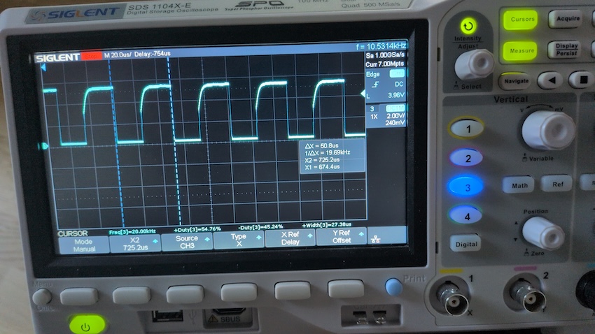
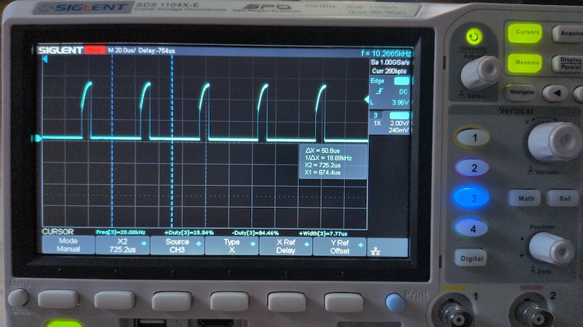
The fan was running at 100% only, regardless of the PWM setting. I started to read the forum, tinkered with the OS and software - nothing helped. Yesterday evening i pulled out my oscilloscope and what do I see? Some nice, proper PWM signal on the PWM pin…
I went to the Aliexpress website and wanted a refund - 2 days too late. I left an angry 1-star review and called it a day.
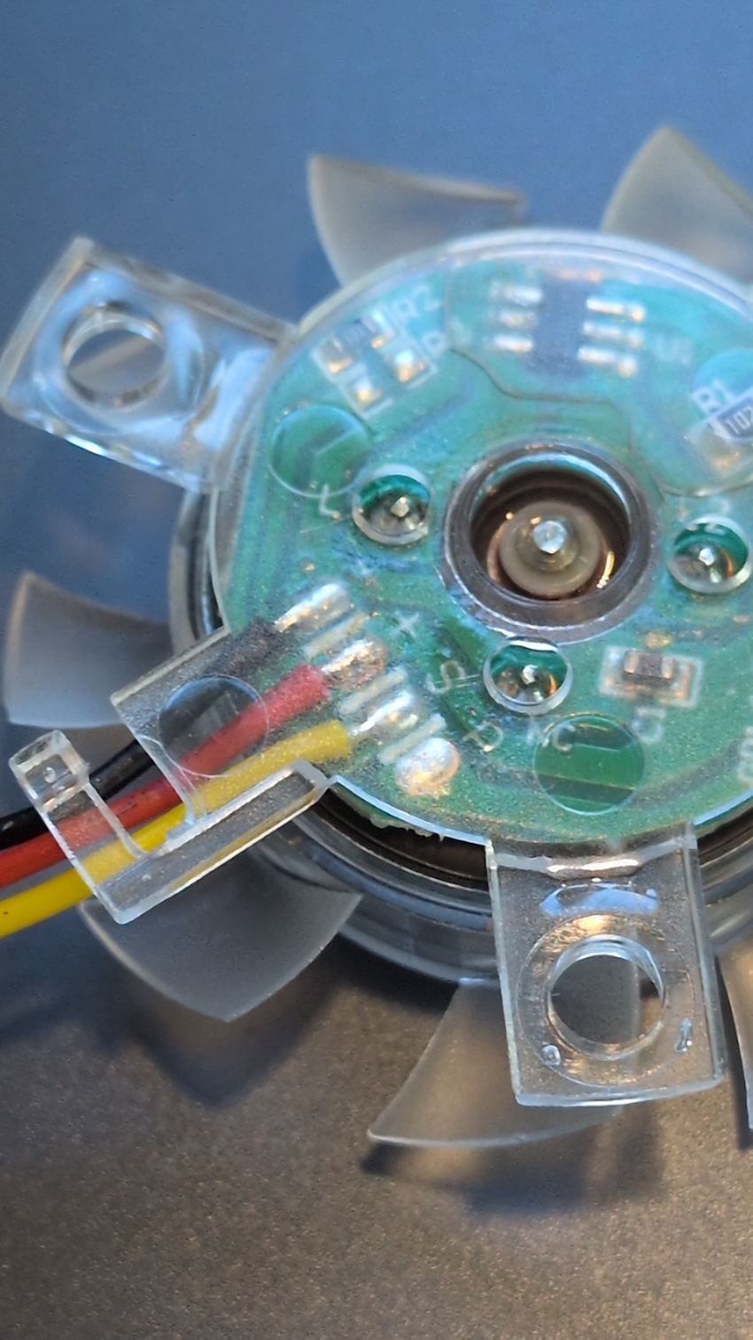
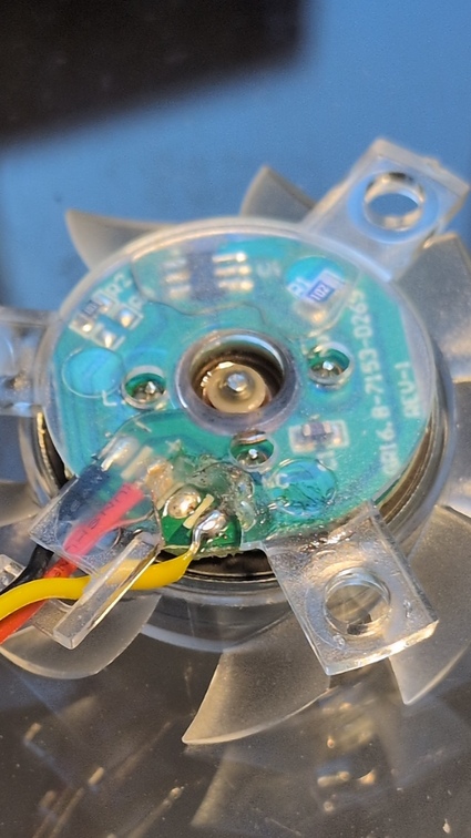
Today, when storing my oscilloscope i felt the urge t to take a look at the fan itself. See the picture yourself… take a close look…
.
…
…
Yeah! Those bozos soldered the PWM cable to the sense contact (‘S’)! After a little hackish soldering the fan works fine. So - when you ordered a heat sink with a ‘transparent’ fan marketed as a “BananaPI BPI R4 PWM Fan” and it’s not working properly - have a look at the wiring/soldering.
FYI - the encasing of the fan seems to be hard/impossible to disassemble, so i chipped off some of the plastic with a small side cutter to expose the pads, because i had the impression that anything else would break the fan entirely.
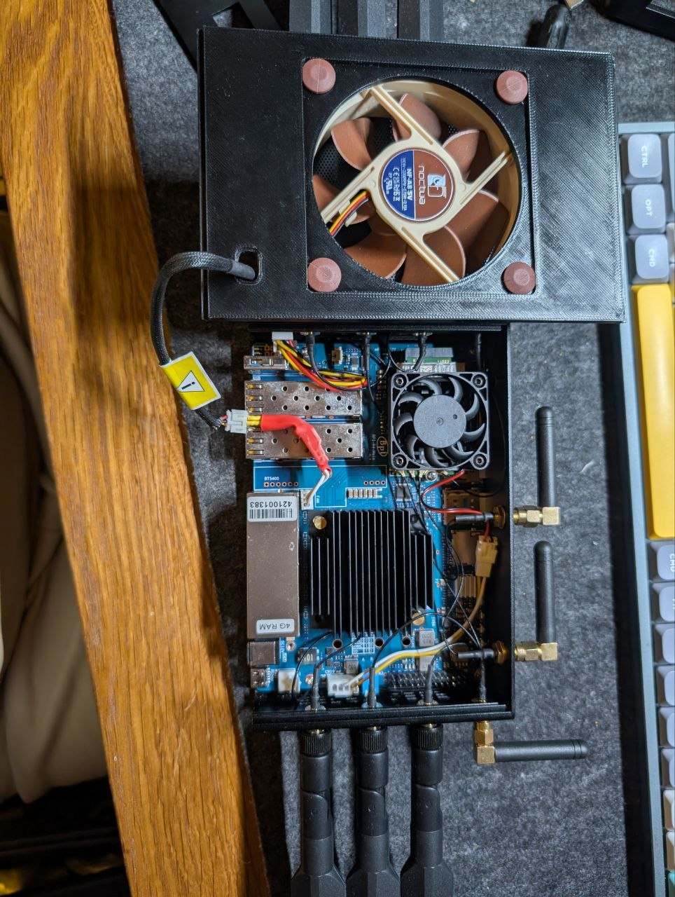
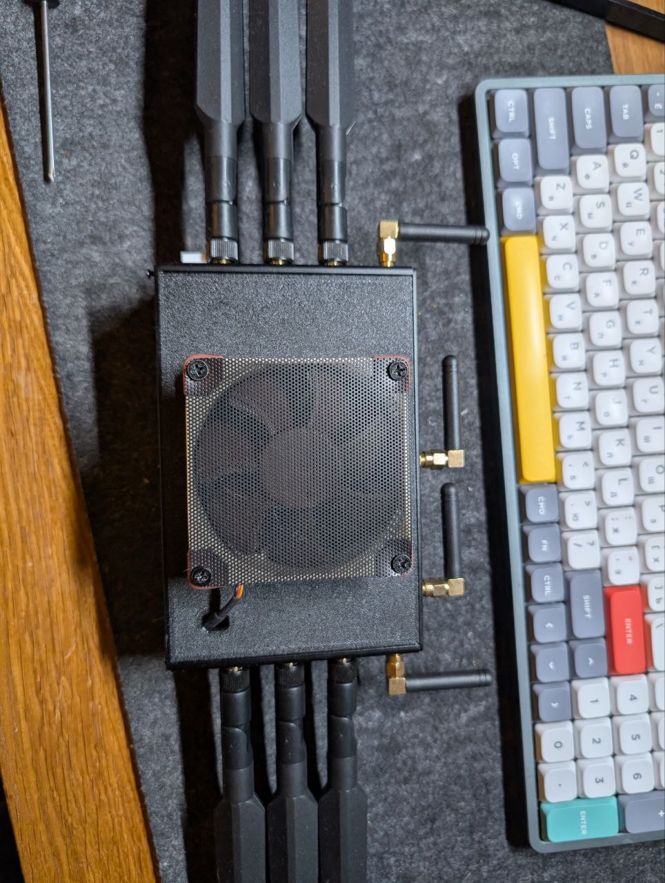
Hello, I have solved the cooling problem based on the example from the messages above. I’ve finalized the idea and tested it, and now I’m ready to share it.
I decided to make the mode silent, so I made DC 3.9V - this is enough for cooling and a little noise. I do not recommend using the standard 3.3V, because the cooler is running at a minimum and there is no cooling. I managed to achieve an angle of 40 °
I’m attaching a 3D printing model of the panel that you see in the picture. CoolPanelV2.3mf (215,3 КБ)