Hello folks,
I am a design engineer currently working on a project involving a BPI M4 Zero to be installed onboard a custom PCB, so I’m checking its documentation in order to wire some signals.
After measurement, we found that the ones on the schematic are correct and the ones on the wiki are incorrect. We will be making changes to the documentation. Thank YOU for your CORRECTION!!
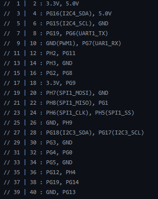
Hi guys! I have Banana PI M4 Zero board and the 40 pin header pinout does not match the one specified here Banana Pi BPI-M4 Zero | BananaPi Docs and in schematic.
The real pinout looks like so:
Could you please upload the correct schematic? Maybe it’s different board revision?
Thank you!
I am currently working on a network security monitoring project that will deploy BPI-M4 Zero boards .
I am very interested in utilizing the 100Mbps Ethernet capability available through the 24-pin FPC connector on the BPI-M4 Zero.
According to the official documentation, the 24-pin FPC connector includes:
Pin 3: EPHY_RXN (Ethernet RX Negative)
Pin 4: EPHY_RXP (Ethernet RX Positive)
Pin 5: EPHY_TXN (Ethernet TX Negative)
Pin 6: EPHY_TXP (Ethernet TX Positive)
I currently have the FPC-24P 0.5mm breakout board that exposes all 24 pins to standard headers. However, I need a solution that includes the Ethernet transformer/magnetics and RJ45 jack to make the Ethernet port functional.
My questions:
Can you recommend any third-party solutions or provide guidance on creating a custom breakout board with the necessary Ethernet magnetics?
I would greatly appreciate any guidance or product recommendations you can provide.