I would think so, but I guess my second method using an user overlay is the better option. By mixing dtb files made from different kernel versions there IMHO is a risk to breaking other things at the same time. No feedback on my question ‘how to do best’ at armbian forum so far …
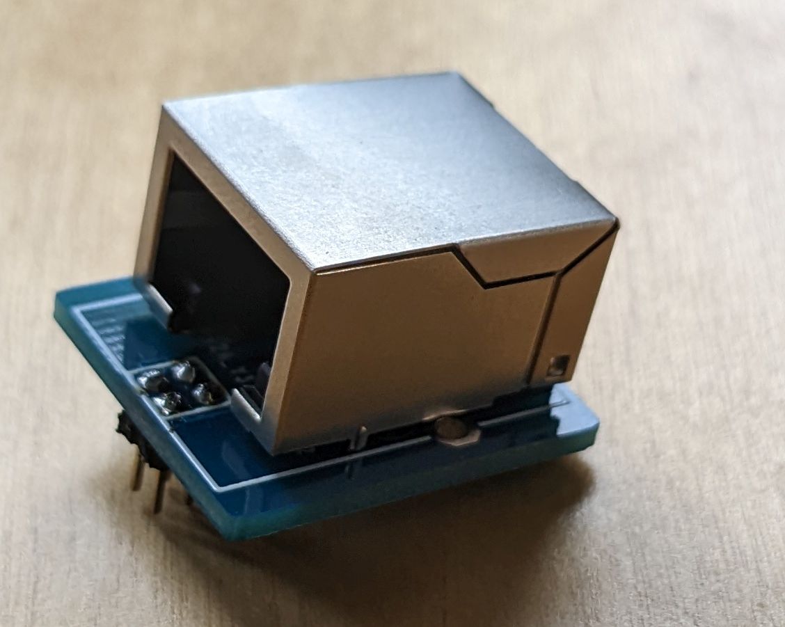
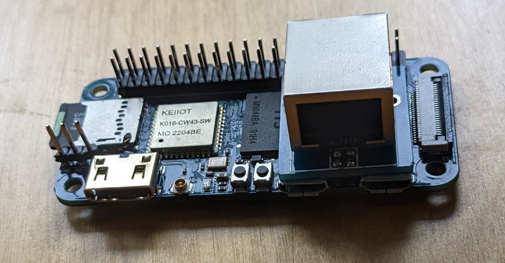
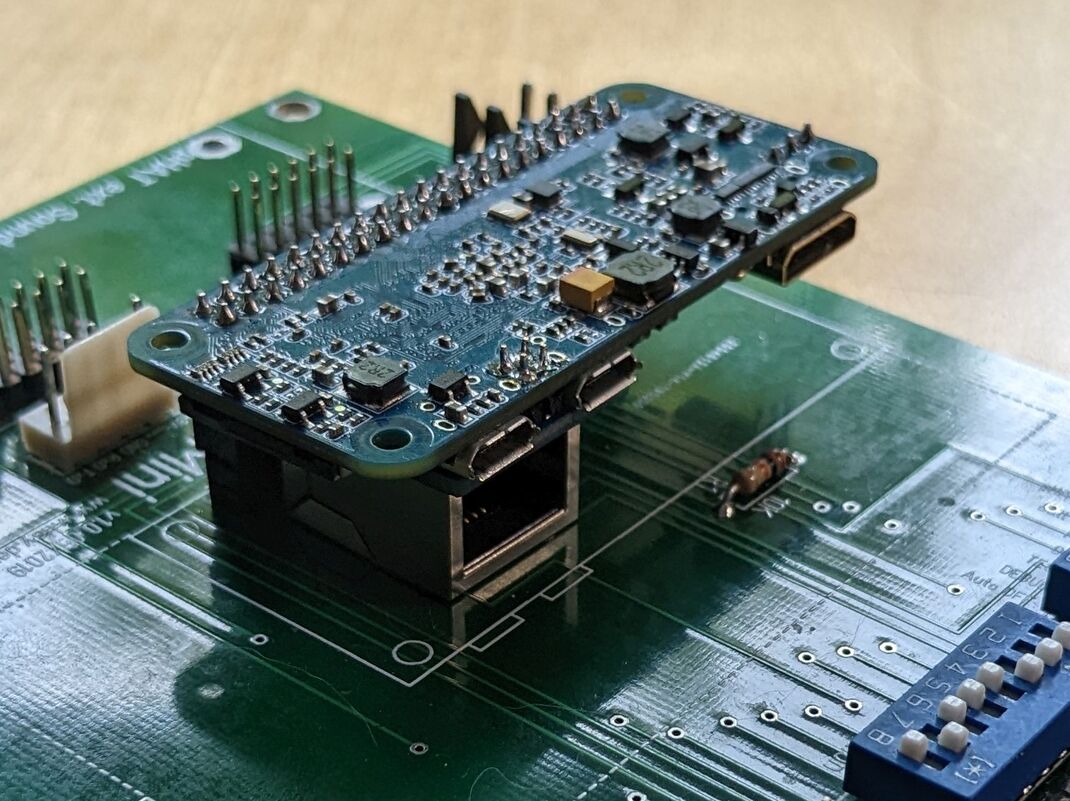
Adapter is ready
More information, including Gerber data for making your own adapter and an armbian image which has the connector enabled by default on my website: https://lisy.dev/banana-pi-m2-zero.html
and the M2 zero still fits on an PCB by using an ‘extra tall header’
Hello Bontango,
for an important project (PLC communication) I urgently need to activate a high speed active ethernet port on the banana pi zero board.
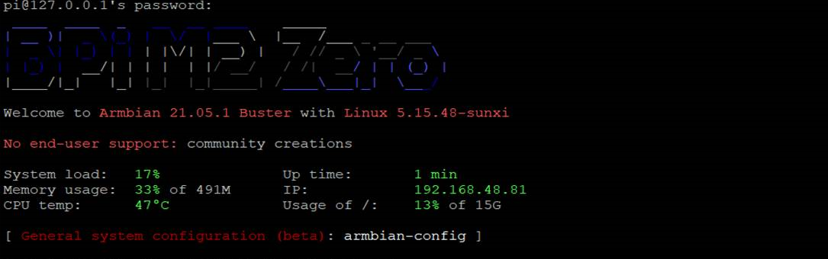
I have the minimal Armbian Buster 21.05.1 image running:
Can you tell me if how can I make it work, I would like to quickly buy your Ethernet adapter with fast shipping. I would like to solder it straight on the board, I would be happy if you would show me the software procedure and a simple schematic for connecting the pins.
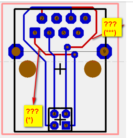
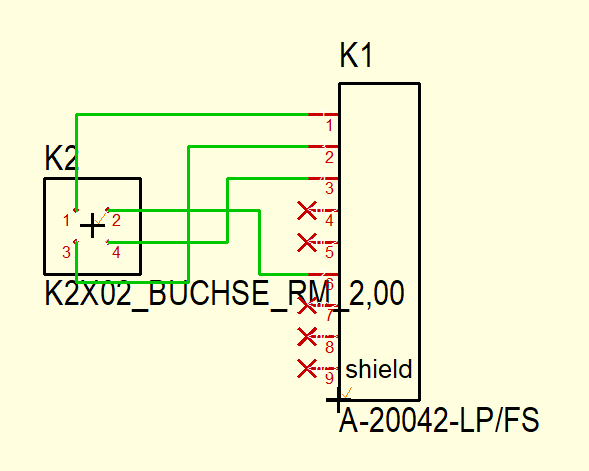
See below the schematics. 1(bpi) -> 1(RJ45) & 3(bpi) ->2(RJ45)
The PCB is a two layer. Blue lines are on top & red lines are at the bottom.
You do not need additional software, the drivers are included in the armbian server image. ( Not sure if it is the case for the minimal image, but the ‘bigger’ one do work) I’m using a ‘self built’ image based on latest kernel which you can find here https://lisy.dev/swrep/BananaPI/images/ )
You can list the interfaces with ‘ip a’. Even without a connection it should show you eth0 interface.
Wish you success, and pls. let us know if it worked for you.
From what I see in the new schematic just connect simply:
pin 1 (bpi) to pin 1 (rj45)
pin 3 (bpi) to pin 2 (rj45)
I didn’t quite understand those red lines (PCB schematic posted above) if they indicate GND (-) connections or what (???*).
They created the doubt to make the simple flying connection on the bpi card to the rj45 connector.
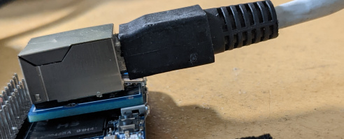
Today the rj45 connector arrives and I make the connection.
I will directly upload the “m2-zero-eth0.dtbo” file already compiled in /boot/overlay-user.
I’ll update you if it works.
an additional question.
Could you tell me a supplier (Europe online store) where you can stock up and buy the rj45 connectors for the bpi-m2-zero board already pre-soldered on the pcb, all ready (rj45 + pcb ready to use).
We would need large quantities of rj45 already pre-soldered ready.
They do also preassembling, HOWEVER my PCB would need small corrections as I found out that the adapter I choosed do not fit 100%. By soldering yourself you can correct that, but external assembly would reject it …
I have already pre-ordered 5 test PCBs.
So they also do full assembly?
What do you advise me to do, I have to ask him if it is possible to make a revision price of the order with complete pre-assembly?
you could upload the updated greber.zip file to repo.
Since they have not yet started creating the PCBs I can tell them to add the pre-assembly of the rj45 connector
That would be a new order as for pre assembly a ‘BOM’ and a ‘CPL’ file is needed in addition. I can have a look which of their RJ45 connectors do fit and create a new revision of my board with BOM & CPL included. Can do it probably already today, so if you want to have assembly I would advise to cancel your current order and wait a bit … let you know.
 Can you tell me if how can I make it work, I would like to quickly buy your Ethernet adapter with fast shipping. I would like to solder it straight on the board, I would be happy if you would show me the software procedure and a simple schematic for connecting the pins.