All the necessary files, BOM, printing and assembly instructions are available on my MakerWorld page. This has been a huge undertaking for me, and I hope other people find the result useful. Feel free to comment and make suggestions for improvement.
P.S. The guy who did laser cutting for me somehow managed to mess up the dimensions of the grounding strips, as seen in the pictures. The DXF drawings are still correct.
Change log
v.1.1.0
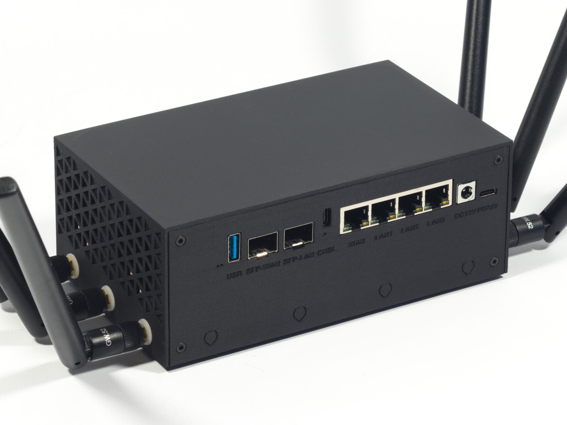
Added back plates for the 2.5GbE version. Can’t test for fit, as I don’t have a 2.5GbE version to verify dimensions. Adjust the STEP file if necessary. There’s also not enough room to use the PoE module and TTL to USB adapter in the same device and I gave up on finding alternative placement for the adapter.
Corrected an error which made one of the baked-in support fins on the back plate disconnect from the model after slicing.
Revised and expanded documentation.
v1.2.0
Added part variants for the 5x3 antenna arrangement.
Added printable washers for SMA connectors.
Restored supports for the back plates, some of which were missing in v1.1.0.
Yes, you can move the SMA port openings by editing the main body and the back panel in CAD.
You can get an instant quote from PCBWay after uploading the parts you need. It might end up on the expensive side, but I’ve only heard good things about their 3D-printing services. Another possibility would be to find a person with the same printer I used or a similar one (thankfully, Bambu Lab devices are quite popular) and ask to pay for their time and materials. That way you can simply use my print profile from MakerWorld and be assured the print comes out as intended.
The RPM oscillates between 50 and 70 % to keep the temps under 50 °C. I can’t hear the fans from a 1 meter distance at all. The stock SoC cooler was silent for me, too, though.
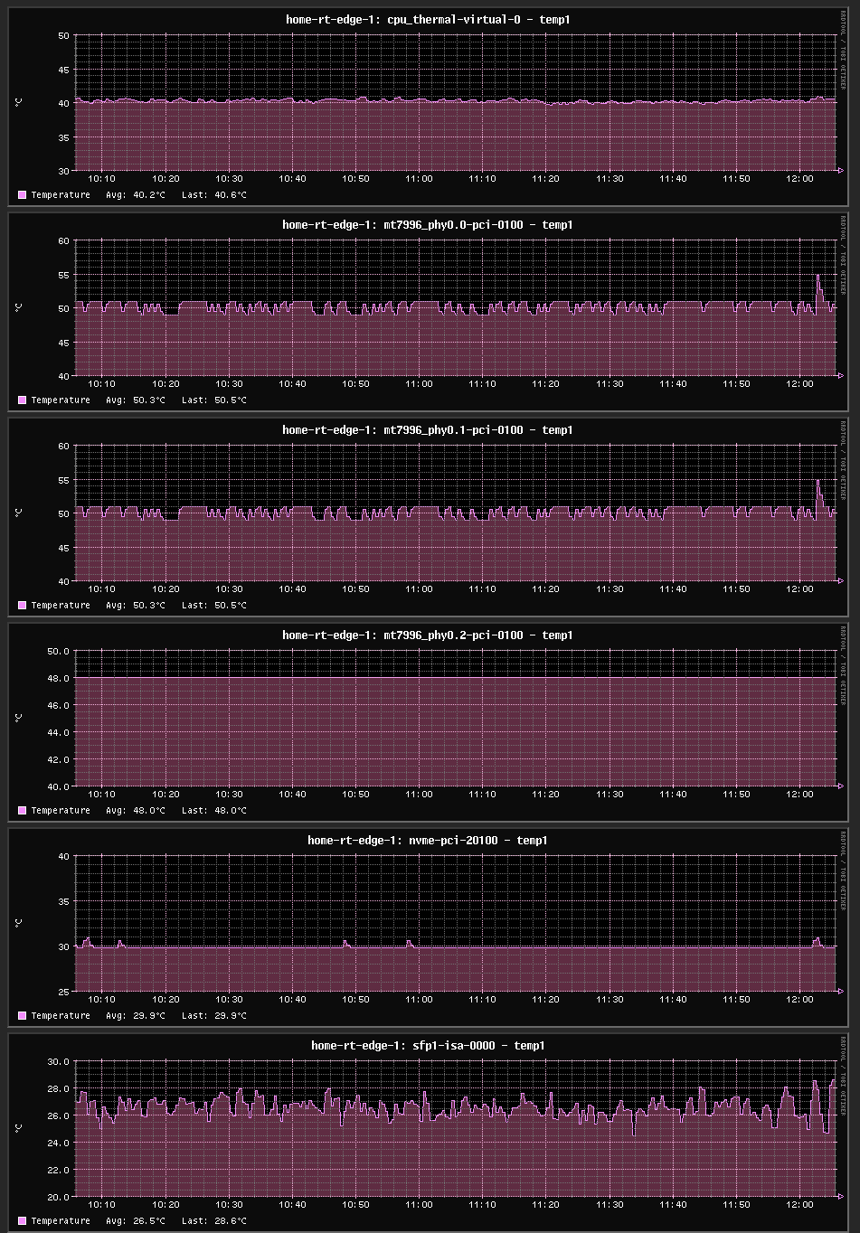
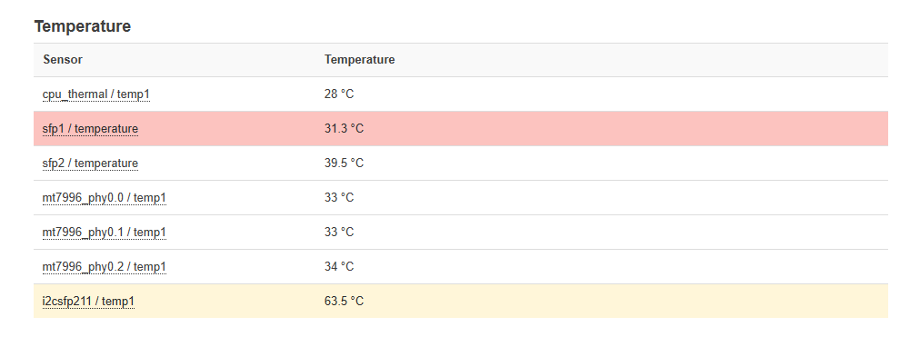
Good afternoon, thanks again for your explanation. With 2.5GB, I had temperatures of 40 degrees, with 5GB, I got 50 degrees, and with 10GB symmetrical, which is what I have contracted, I get 63.5 degrees. Before, I got about 68 degrees. But with the latest modification, these are my 24/7/365 temperatures. The temperature in pink is 10Gb XGS-PON ONU SFP 8311-was-110, which is the one I use for the fiber that brings home. XGS-PON ONU SFP+ Stick with web management MAC 10Gbps SC/APC 1270/1577nm -40 to 85°C Industrial grade SMF 10G/10G XGSPON ONT.
I’m leaving you an image of the temperature of the main router in the house.
Big thanks for doing this. This looks amazing. Smart idea to include the serial to USB Adapter.
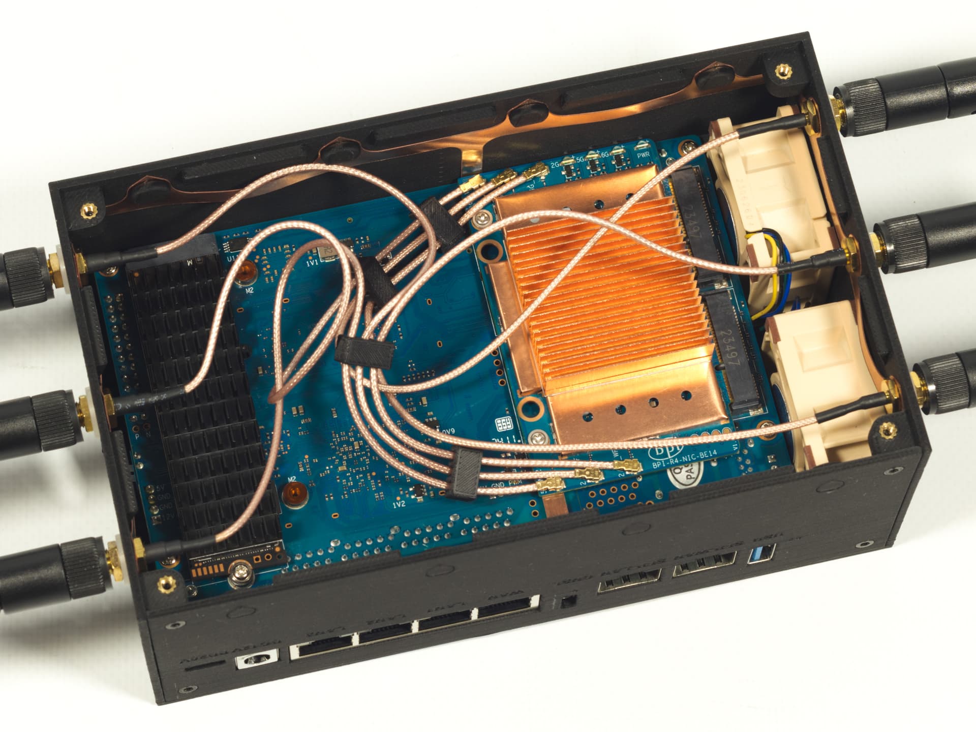
And that heatsink for the wifi NIC looks crazy good and effective.
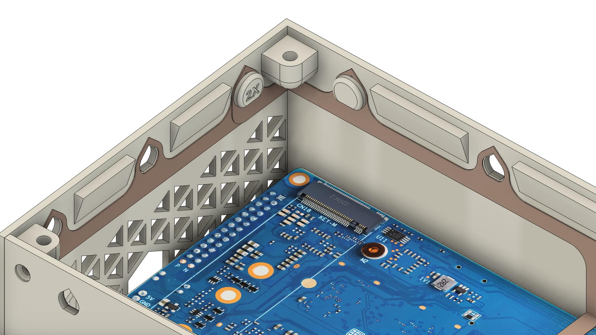
Only one thing (of course ) it looks like the space between CPU and case is very small. Did you have a heat sink at the cpu? I also use a 5g modem which gets very hot, without a heatsink this is not possible. If the board and the fans would be exactly in the middle than you would have enough space for both sides.
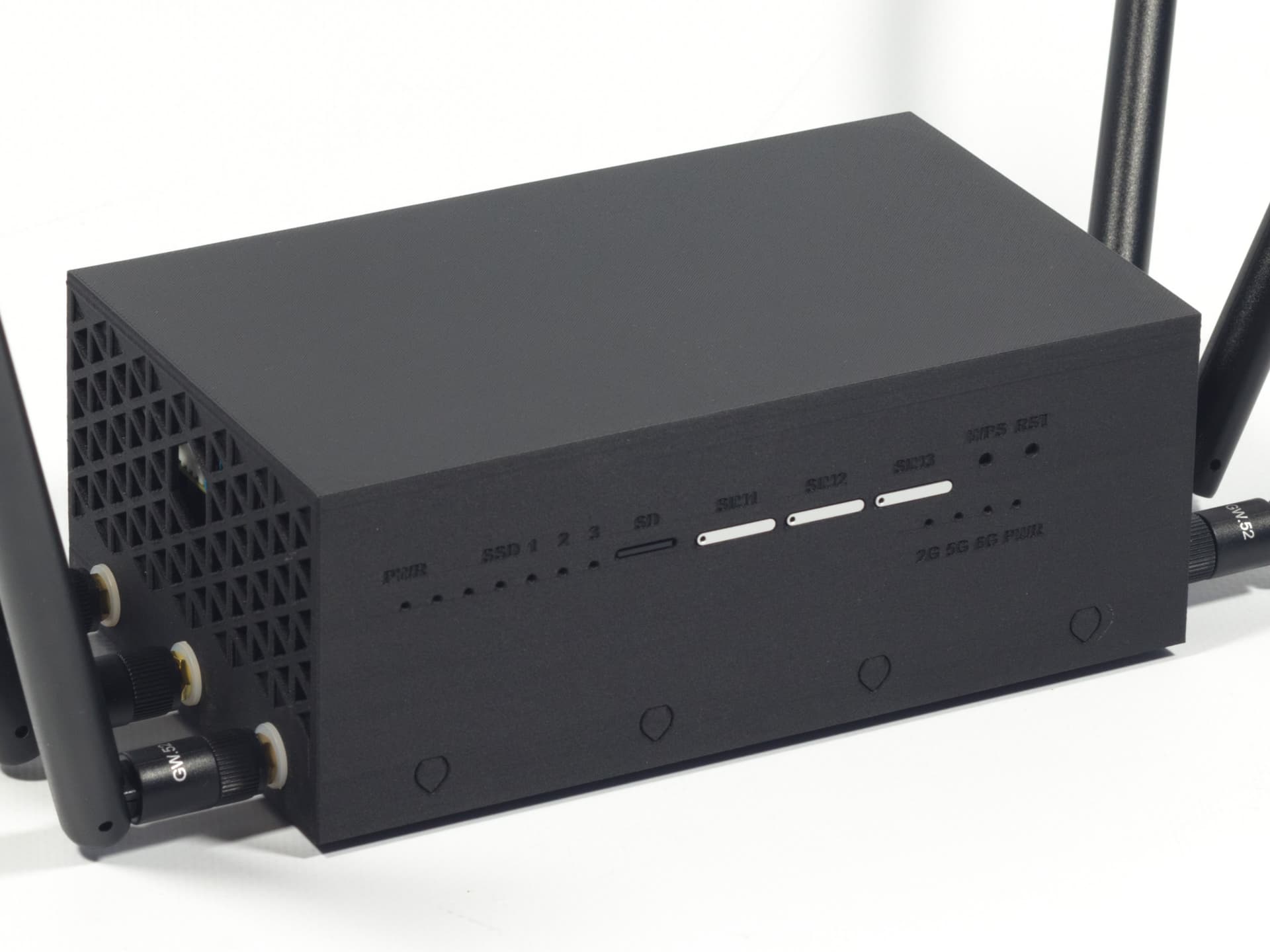
The antenna ground and the port for UART is a very nice idea
There’s 22.8 mm of clearance between the PCB and the case on the SoC side (not counting the SoC package height). This is plenty for a 15 mm tall heatsink, which is what I used.
Of course for the cpu, this is not the problem, but the 5g modem on the m2 socket is about 1cm above the board. But maybe with the airflow is enought the queltec rm520n gets about 60 degrees without heat sink (75 is allowed max)
However, @sinovoip should get inspired by your case design
A 5–7 mm tall copper heatsink for the modem should, hopefully, be good enough. I’m going to try it with a 4G modem, which I bought recently, and see how it goes.
This case design is very good and i think it fits nice to the board design. Left fan is blowing above sfp and cpu, right fan above modem and ram. So with a tiny heat sink it should be enough (it’s just cause i have 11mm copper height plates at home )
This case gives me a lot of inspiration Best solution would be to combine modem and cpu heatsinks somehow (saw that long time ago with a round copper bridge for an asus mother board to cool north and south bridge with one heat sink)
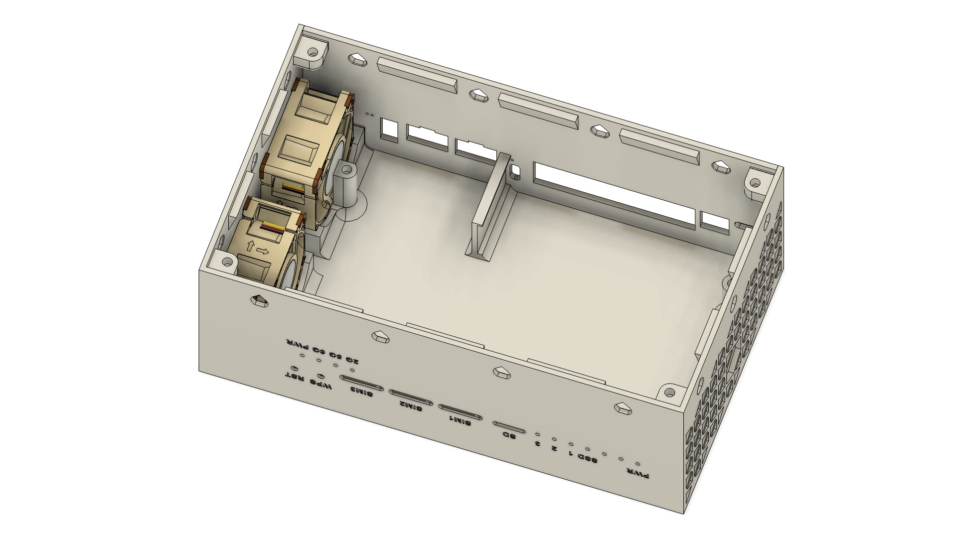
Are the fans screwed? Or only fixed by the case? Cause something like a optional dust filter would be also a very special feature i think
Each of the fans is slotted into its own holder, which secures it horizontally, then the studs sticking out of the bottom part keep the fans from moving vertically. So, no screws. Dust filters would be a good addition, I’ll give it a thought. Thankfully, the holders are slightly oversized, so they could accommodate a very thin mesh. Better yet would be to make circular 3D-printed frames for the Noctua fans, which would hold a mesh (like a window fly screen) and sit flush agains the surface.
I was considering doing that after buying a 2.5 GbE version, but I ended up getting another 2xSFP+ and can no longer verify the dimensions of the back panel for tight fit. If you have one on hand, you can actually help with that by measuring the width of the 2.5 GbE connector housing and the height (from the PCB or together with the PCB) as accurately as possible with calipers. The official DXF is of little help here, as the manufacturer can change parts suppliers freely.
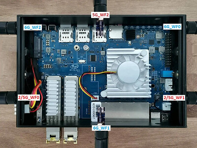
If you can, and doing custom case, you can and make special pockets in side walls, avoid antena cables going across the PCB, route those straight over the edge and then to the connector.
This is a neat idea. But in this case, the pigtails absolutely have to be facing away from the Mini PCIe connectors to avoid picking up RF noise from the main PCB.
I’ll attempt the project very soon, just one clarification. You mention to source “2 × Noctua NF-A4x20 5V PWM”, but these are 4-pin fans, and in the guide you only say to plug 3 “The fans can be connected in parallel to the GPIO header instead; pin 4 is 5V, pin 6 is GND, and PIN 7 is PWM;”.