Wifi stops working when SFP module is added on BPI-R3

I’ve installed the latest OpenWRT version 23.05.0-rc3 and, when I connect one (or two) SFP Modules, I get this error and the wifi stops working:

mt798x-wmac: probe of 18000000.wifi failed with error -110

The SFP module I have is 2.5G Copper: SFP-2.5G-T-R-RM. The connection works properly and I see this on the logs:

sfp sfp1: Host maximum power 1.0W
sfp sfp2: Host maximum power 1.0W

As soon as I remove the modules, the wifi starts working.

Have you the issue also without cable connected? I noticed sdcard issues in uboot when i connect cable to my 2g5 sfp.

I tested multiple scenarios, but they all failed.

  1. 1 SFP module installed, no cable
  2. 2 SFP modules installed, no cable
  3. 1 SFP module installed, cable connected
  4. 2 SFP modules installed, 1 cable connected

@frank-w A fun fact about this issue. After trying a couple of times and removing the UART Device (I tried a couple of them, but both were causing the same issue) both SFP ports started working along with the WiFi.

If this is literally an issue with the UART device, I still didn’t get what’s the fix, although I’ve followed this topic

Do you use ftdi uart adapter?

I’ve been using these ones:

Be careful to use only adapters with 3.3v level. And these 2 have issues with r3 (i guess cp21xx is a 2102…2104 are rare)…so better try ftdi…

Is there any workaround with these devices?

In any case which FTDI versions would you recommend?

Maybe you can try this,but i have not tested it:

I have some ft232rl and 2 ft4232 (4 port usb2uart)

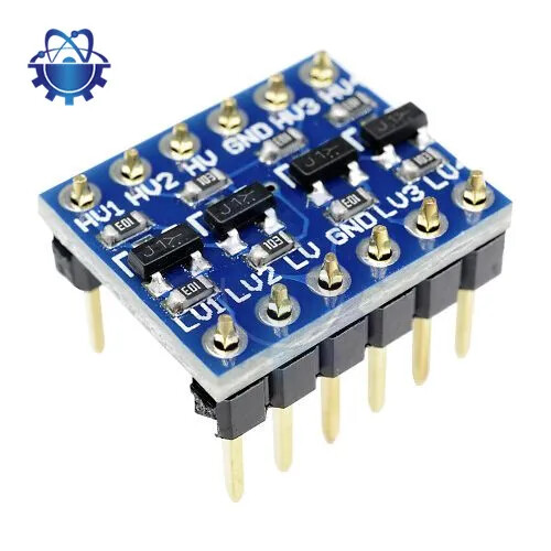
Perhapse you can use an i2c level shifter. You can use it, even if the high voltage side is also 3.3v. If it isn’t working immediately, at least you can change the pull-up resistance on these shifters

Hey @ericwoud could you share how I could share some sort of diagram or images of how that’d look like? My electrical skills are on the basics level so I’m not being able to envision both your suggestion or the one on GH that @frank-w linked.

My BPI-R3 kit came with the UART connection thingy. Never had to use it. Perhaps they sell it separately?

https://learn.sparkfun.com/tutorials/bi-directional-logic-level-converter-hookup-guide/all

Basicly levelshifters transforming an input signal to another voltage (e.g. 3.3v input to 5v output or vice versa)

Here you may stay at 3v3,so LV and HV are both 3.3v…this only done to change the pullup resistor if the one from your adapter is too small

Most adapters having 5v and 3.3v pins which you can use for LV and HV

levelshifte1r

levelshifter2

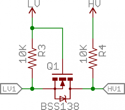
These are bi-directional, so you can use them for RX an TX. Standard 10k pullup, this might already be large enough. Now I doubt if it is true that on HV you could also use 3.3V. You could try, but if that does not work, you can use all 4 shifters. So 3.3V - 5V - 3.3V, since there are 4 on the board anyway.

But if 10k is high enough, I believe the ESP has similar high internal pullups.

Edit:

In the datasheet it says:

The isolation feature can also be applied if no level shifting is required, VDD1 and VDD2 may have the same value, e.g. both 3.3V or both 5V.

That’s really darn cool piece of information @frank-w and @ericwoud . I really appreciate your time guiding us on how to do that. I’ll see if I buy some of these and attach it to to the TX RX (and probably GND as well, right?) to the UART interface to see how that goes.

Don’t forget the 3.3V,to LV and HV or perhapse 3.3V to LV and 5V to HV, depending on how you use it

Be careful with 5v…do not put 5v on HV when HVx is connected to the board

See LV/HV more like voltage in and voltage out (or voltage 1 and 2). So the sides of the levelshifter…

Correct, HV with 5Volt then HV!/HV2/HV3/HV4 would not be on the BPI-R3 side…

I would always put LV1/LV2/LV3/LV4 on the BPI-R3 side, as it will be isolated when powered down.

So in practical terms, guess we’re saying the setup should looks like this?

BPI --------------  Level Shifter   ---------- CH340 (or others)
RX --------------  LV1 <--> HV1  ---------- TX
TX --------------  LV2 <--> HV2  ---------- RX
GND --------------  GND <--> GND  ---------- GND

Yes,but you have to connect LV/HV (without numbers) too…should be both 3v3 from your usb adapter if it is already 3v3. If adapter has 5v ttl HV needs 5v