What SD image you use? And check boot jumper on board.
I use bpi-copy 2020-04-09-OpenWRT-mtk-bpi-r64-SD.img /dev/mmcblk0p1 I tried with both positions of the Boot select jumper. thanks
Output shows only bootrom…maybe sdcard not recognized or missing headers
i try different SD card. I use http://wiki.banana-pi.org/Getting_Started_with_R64#How_to_burn_image_to_SD_card :
Warning: Try to write 2020-04-09-OpenWRT-mtk-bpi-r64-SD.img to BOOTDISK /dev/mmcblk0p1
==============================================================
Fri May  7 05:57:26 PM EEST 2021
*** start COPY (blue led on ) .....
INFO: /dev/mmcblk0p1 : SD/eMMC !!
umount device: /dev/mmcblk0p1
==============================================================
IMGFILE=2020-04-09-OpenWRT-mtk-bpi-r64-SD.img
==============================================================
img
1+1 records in
1+1 records out
20191432 bytes (20 MB, 19 MiB) copied, 0.152421 s, 132 MB/s
19.3MiB 0:00:00 [ 126MiB/s] [ <=>                                                                ]
0+309 records in
0+309 records out
***  end  COPY (blue led off) .....
Fri May  7 05:57:32 PM EEST 2021
==============================================================
RUNTIME 0:6
OK!! You can remove the BOOTDISK /dev/mmcblk0p1 now!!
But result same:
F0: 102B 0000
F5: 4801 0000
F5: 480A 0031
F3: 4000 0036
F2: 300C 0000
00: 1005 0000
F5: 480A 0031
F5: 480A 0031
F3: 4000 0036
F2: 300C 0000
01: 102A 0001
02: 1005 0000
BP: 0000 00C0 [0001]
T0: 0000 040A [000F]
System halt!
thanks
Maybe you should try stock OpenWRT image bananapi_bpi-r64-sdcard.img.gz . And how you flash image to SD? I am use win32diskimager.
Have you unpacked the image before writing? Is sdcard correctly inserted?
Just tried the image:
SRC=openwrt-mediatek-mt7622-bananapi_bpi-r64-sdcard.img
DST=/dev/mmcblk0p1
COPYMODE=imagetodisk
imagetodisk
bpi-copy(v1.3.4(github)), bananapi image & disk tools

Usage: bpi-copy [OPTIONS]...
   bpi-copy [ --help | -v | --version ]
   bpi-copy IMGFILE
   bpi-copy IMGDIR
   bpi-copy IMGFILE DEVICE
   bpi-copy DEVICE IMGFILE

Warning: Try to write openwrt-mediatek-mt7622-bananapi_bpi-r64-sdcard.img to BOOTDISK /dev/mmcblk0p1
==============================================================
Fri May  7 07:35:25 PM EEST 2021
*** start COPY (blue led on ) .....
INFO: /dev/mmcblk0p1 : SD/eMMC !!
umount device: /dev/mmcblk0p1
==============================================================
IMGFILE=openwrt-mediatek-mt7622-bananapi_bpi-r64-sdcard.img
==============================================================
img
5+1 records in
5+1 records out
57033010 bytes (57 MB, 54 MiB) copied, 0.429704 s, 133 MB/s
54.4MiB 0:00:00 [ 121MiB/s] [ <=>                                                                ]
0+871 records in
0+871 records out
***  end  COPY (blue led off) .....
Fri May  7 07:35:38 PM EEST 2021
==============================================================
RUNTIME 0:13
OK!! You can remove the BOOTDISK /dev/mmcblk0p1 now!!
The output after ~5min on press 10sec Power/Recovery or after Reset immediately:
F0: 102B 0000
F5: 4801 0000
F5: 480A 0031
F3: 4000 0036
F2: 300C 0000
00: 1005 0000
F5: 480A 0031
F5: 480A 0031
F3: 4000 0036
F2: 300C 0000
01: 102A 0001
02: 1005 0000
BP: 0000 00C0 [0001]
T0: 0000 040A [000F]
System halt!

Thanks.Have unpacked openwrt-mediatek-mt7622-bananapi_bpi-r64-sdcard.img.gz and the 2020-04-09-OpenWRT-mtk-bpi-r64-SD.img wrote as is. SD card can be inserted with lock one way or stuck on half way. thanks
There is a spring mechanism,if correctly inserted you only see ~3mm from the card
Yes, press to insert with click and press with click to eject.
Which device do you use to write? Your flashlog seems to be the r64 itself…dpes sdcard boot work and emmc not? Above you’ve wrote you want to boot sdcard,but flashing uses /dev/mmcblkX normal pc has /dev/sdX
So please look which device should be written (e.g. dmesg after inserting card into pc) and call bpitools with this (or change config)
bpi-copy IMGFILE /dev/sdx
I guess your sdcard is empty
Boot BPI64:
BusyBox v1.25.1 () built-in shell (ash)

     _________
    /        /\      _    ___ ___  ___
   /  LE    /  \    | |  | __|   \| __|
  /    DE  /    \   | |__| _|| |) | _|
 /________/  LE  \  |____|___|___/|___|                      lede-project.org
 \        \   DE /
  \    LE  \    /  -----------------------------------------------------------
   \  DE    \  /    Reboot (17.01-SNAPSHOT, r0-637c6d18)
    \________\/    -----------------------------------------------------------
I use Linux laptop with card reader to write. lsblk looks like:
mmcblk0     disk                                                              488.5M
└─mmcblk0p1 part
My fault was /dev/mmcblkX or mmcblk0p1. I changed copy command to:
bpi-copy IMGFILE /dev/mmcblk0
Very very appreciated! Thanks
I was looking for a USB-C board which has 4 holes for mounting. I want to give a short overview of my research:
For me, the best board I found (on the first view) was that:
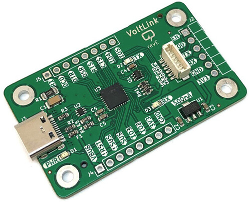
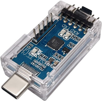
But I just say this, because it is the same chip like in my DSD TECH SH-U09B3. It is the CP2102N from Silicon Labs (https://www.silabs.com/):
I have not testet any of the boards jet! So good luck!
If someone fonud some other boards for usb to TTL please post it!
Check this GitHub - tigard-tools/tigard: An FTDI FT2232H-based multi-protocol tool for hardware hacking
1 Like
It’s a good link ![]() :
:
THIS PCB should definitly on our list ![]() .
.
Originally i was looking for a cheap, but reliable usb to UART PCB which I can mount beneath my R3 and R4. For this purpose it is oversized. I already feel bad because I spend so much money to something that I already have. But I’m to lazy always go for the USB to TTL adapter …
But come back to this PCB. It maches all the others!?
It doesn’t have too cost much, this will do nicely, also on R3:
https://www.aliexpress.com/item/32650148276.html
Just absolutely make sure to set the jumper to 3.3V before using it!!!
My problem is the mounting:
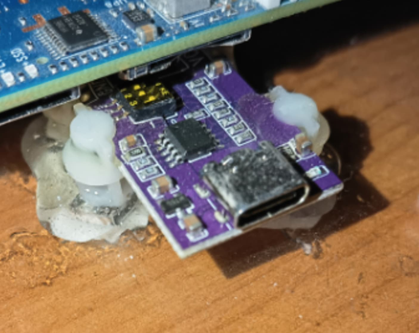
This was my first try. And it will be my last! Sure there are possibilities to fix it in a good way … but I spend to much time for the mechanical things …
My problem with your board is the price!:
The last days I read much about fake chips … I’m not sure about it …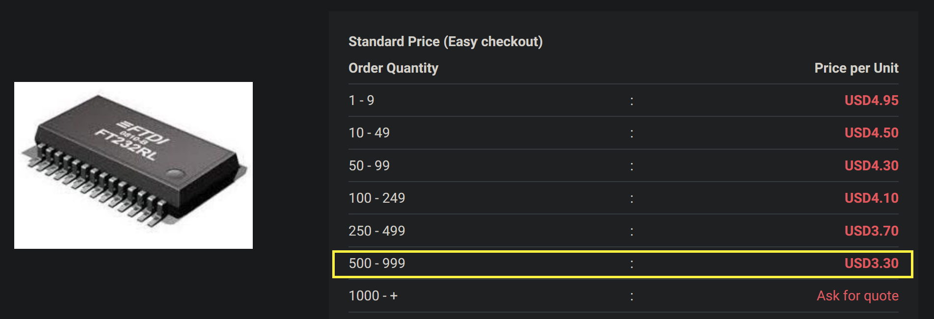
In general, I was looking for:
→ newest chips + original (FT232RL, CP2102N, CH340? …)
→ four mounting holes within the PCB (I prefer metalized)
→ a PCB design, that can not harm my PC
II thought there would be a specialized company who produce this board with all available chips and a good datasheet. But there are “just” single project. You have to be lucky to find your chip of choice. And I felt a bit saver If the board have revisions numbers. Because that means that the seller is interested in this things!
For debugging I will find a board … but I also look for USB PD and would prefer PD 3.1 and this is not good looking!
In my experience, even these cheap ones work without any problems.
The only thing to look for is on the R3, to use one with large enough pullups inside, like the ft232, even the cheap ones seem ok.
1 Like
First of all,
what is your scenario?
Your board, your adapter and how you connect it TX, RX, GND … .