I have recently started looking into a Banana PI R4 board and am running into a boot issue. I have listed the steps I have undertaken below.
I looked into the documentation for Banana PI R4 board for SD card boot. I have performed the following and followed the documentation.
keep the dip switches to (1,1) as suggested by documentation for SD boot
use dd to write zeroes to the SD card and later flash the image on to the SD card. Tried with BalenaEtcher too.
Since the WiFi card is attached, move the SW4 to ON position
connected the USB-toTTL adapter with TX and RX crossed and GND to GND
Once the SD card is inserted and power is provided (12v - 5 A) through the barrel jack, the red lights come up which shows power is coming to the board. But nothing else seems to happen
minicom shows no output (settings 115200/Flow control off/parity none)
No blue light blink (as read in some of the posts) indicating boot is seen.
Can anyone kindly provide any inputs on how to proceed further? Since, minicom is not showing any output and the blue light never comes up, I can only think that the boot process never started. If so, any further actions to take in order to get to know what is happening?
A couple of additional steps also attempted which also did not work
I attempted the boot by removing the WiFi card to see if power was an issue. Did not help.
Tried booting with official image, as well as a self compiled image to see if something was wrong with the image. behaviour is same.
Any inputs will help me to start out on Banana PI R4 and is appreciated
I recall my R4 has factory shipped with a bootable image in the NAND. So you may give it a try without the WiFi module installed.
Also, worth trying without the debug console connected. See if the LEDs light up. Rea always. Then blue. Then Blue transits into Green (which means the kernel is running).
Is the uart adapter 3.3v? Else you can brick the soc. You can measure it with multimeter between tx-gnd when not generating traffic (data pulls tx to gnd).
We checked the datasheet and find that the USB-TTL provides 3.3V logic level as stated below in the datasheet
The power pin provides the 5V @ 500mA direct from the USB port and the RX/TX pins are 3.3V level for interfacing with the most common 3.3V logic level chipsets.
We are using DigiKey - 1528-2128-ND USB to TTL adapter
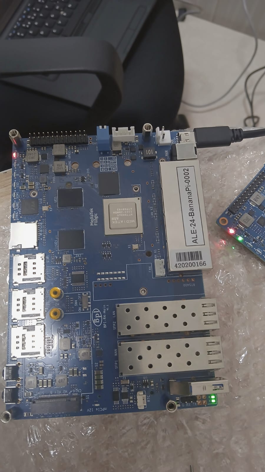
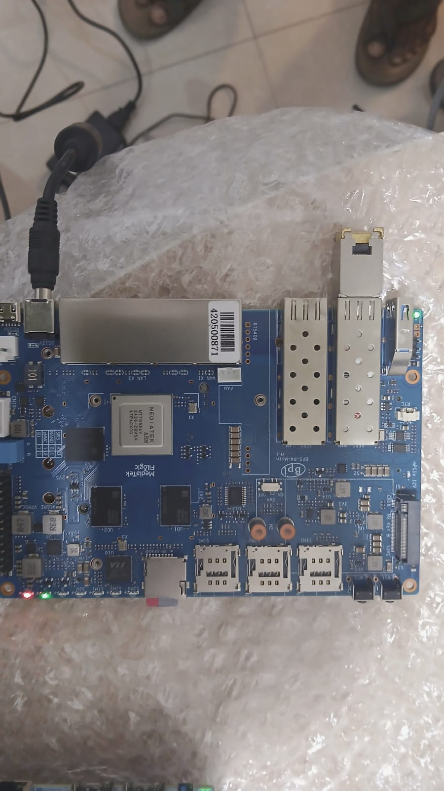
We attempted to bring up another Banana PI R4 and we were successfully able to bring it up with the same steps that fail for the other board. We have a snapshot of the working and the non working board attached.
We see the following in the non-working case:
The LEDs near the UART pins - both are showing green
The red pwr LED button is on and the green LED never comes up
Two of the Ethernet (1 WAN and the other LAN) have green LEDs that are always ON without any ethernet cable connection.
The red PWR LEDs are hardwired, so they’re always on. The two LEDs near the USB ports are for the SFP cage. The green LED (next to the PWR LED) will be turned on by the bootloader.
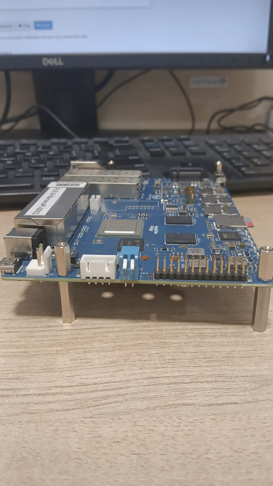
Can you describe the boot mode switches again? According to your first photo, it looks like facing upwards, but the 1-1 position is to face downwards. Up-up (0-0) is an undefined state in this board.
Edit: The green LEDs on the ETH ports are strapping pins when the device is powering on (two of them are related to the boot mode switches, and the other two are for the memory density if I remember correctly). So there are completely normal to signal something before the system is running. After the system boots up, the switch will take over to controlling them.
The DIP switches for SD boot was both were in the down position as mentioned in the Banana PI R4 documentation suggesting 1,1 setting. The same setting worked for the other board which came up for SD card boot.
Thanks for the SFP cage information. Looks like one SFP cage is not getting detected on the working board then.
Here is a snapshot of the non-working board switch position for SD card boot
People had working R4 which suddenly died during winter. The symptom looks very similar to yours. My theory to their problems was electrostatics killing their debug port. Not sure if it’s the same case for you.
You can try to not initialise the debug port aka console during kernel boot. See if this at least get you the G led lit.
This is bootom output which does not find boot-device. Please make sure the boot switches are in the right position and your adcard is correctly flashed and inaerted.
That second board result is very interesting.
However, I would still not completely rule out the SD card itself yet.
On MTK/ARM systems it is actually possible that:
the exact same SD card works on one board then fails on another supposedly identical board, especially during very early boot stages (BootROM / BL2 / SD init).
These boards can be surprisingly sensitive to:
SD card controller differences, signal integrity, timing tolerances, power stability, SD slot tolerances
So the successful second-board test proves the image itself is valid, but not necessarily that the SD card is electrically/timing-wise stable on every board.
Before concluding the board is defective, I would still test:
another high-quality SD card from another SD reader, freshly written image via Linux dd
If a second known-good SD card also fails only on that specific board, then I would start suspecting the board hardware itself.
DIP Switches not doing the “dip’ing” correctly, sd card PIN connection isssue, use another psu, 3.3v Rail stable (e.g. short drop at start)?, naked boot /wo any adapters etc…