The emulated eeprom maybe only functional when the tx is not disabled. Not really according specs, but still…
good point. worth a shot.
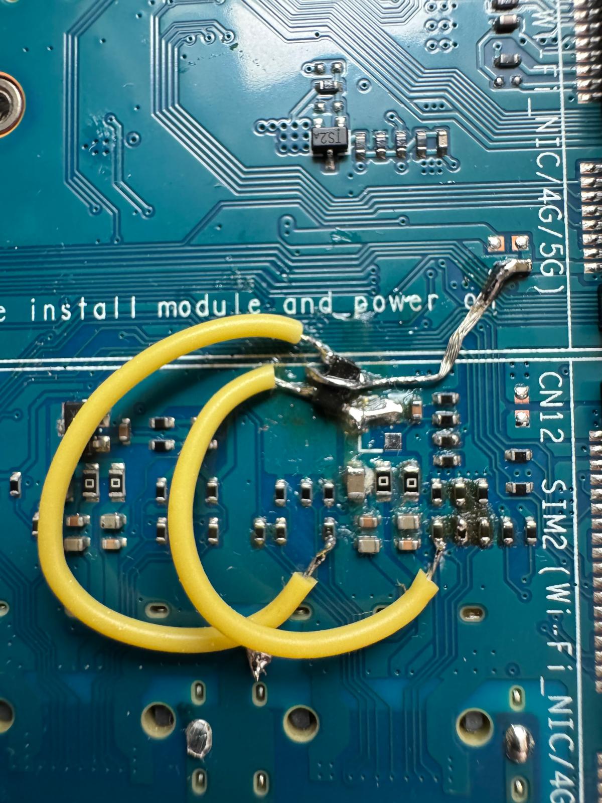
ericwoud: I was the one who removed R106, it should be okay, I can substitute with a piece of wire since it is 0R.
glassdoor: I am hoping to capture the signals between my working setup (mellanox) and bpir4 to compare the pin states during module initialization.
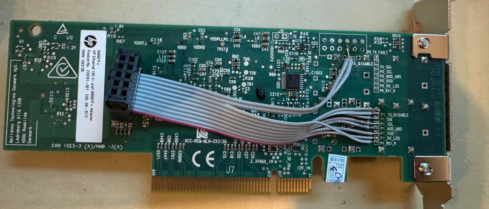
Right now, I’ve soldered leads onto my mellanox card to observe the pin states at the s800e is initialized correctly:
This is what the trace roughly looks like:
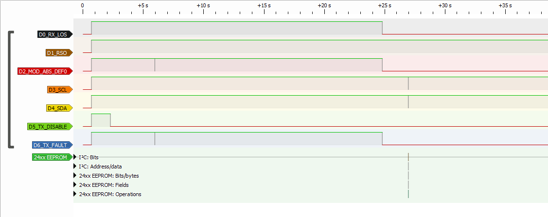
- S800E plugged into ConnectX-3, x86 openwrt, cold start
- Power on at ~0.7s, all pins high
- tx-disable goes low ~2.2s
- ~6s, moddef0 pulses low very briefly, followed by tx-fault pulsing low
- ~25s, LOS goes low, quickly followed by tx-fault, then followed by moddef0
- ~27s, bunch of i2c reads
- no significant signal state changes for ~30s, link appears to be up
i2c reads during setup:
; Identifier
107877393-107878989 24xx EEPROM: Operations: Sequential random read (addr=00, 2 bytes): 03 04

; Transceiver
107879118-107880683 24xx EEPROM: Operations: Sequential random read (addr=07, 2 bytes): 00 00
107880768-107882332 24xx EEPROM: Operations: Sequential random read (addr=08, 2 bytes): 00 00
107882416-107883980 24xx EEPROM: Operations: Sequential random read (addr=09, 2 bytes): 00 00
107884066-107885630 24xx EEPROM: Operations: Sequential random read (addr=0A, 2 bytes): 00 03

107885715-107887279 24xx EEPROM: Operations: Sequential random read (addr=03, 2 bytes): 20 00
107887364-107888928 24xx EEPROM: Operations: Sequential random read (addr=04, 2 bytes): 00 00
107889013-107890577 24xx EEPROM: Operations: Sequential random read (addr=05, 2 bytes): 00 00
107890660-107892225 24xx EEPROM: Operations: Sequential random read (addr=06, 2 bytes): 00 00

107913442-107915007 24xx EEPROM: Operations: Sequential random read (addr=08, 2 bytes): 00 00
107915126-107916691 24xx EEPROM: Operations: Sequential random read (addr=03, 2 bytes): 20 00
107916804-107918368 24xx EEPROM: Operations: Sequential random read (addr=06, 2 bytes): 00 00

; Vendor OUI
107918484-107920049 24xx EEPROM: Operations: Sequential random read (addr=25, 2 bytes): 00 00
107920132-107921696 24xx EEPROM: Operations: Sequential random read (addr=26, 2 bytes): 00 00
107921781-107923346 24xx EEPROM: Operations: Sequential random read (addr=27, 2 bytes): 00 53

; Transceiver
107923460-107925024 24xx EEPROM: Operations: Sequential random read (addr=06, 2 bytes): 00 00
I eventually would like to trace the same for the bpir4 to compare if there are any major differences. In the meantime, an idea to try is to emulate the signals here by hand and see if the module starts up properly?
Edit: uploading the raw pulseview trace here: mlx_boot_export.sr (215.8 KB)
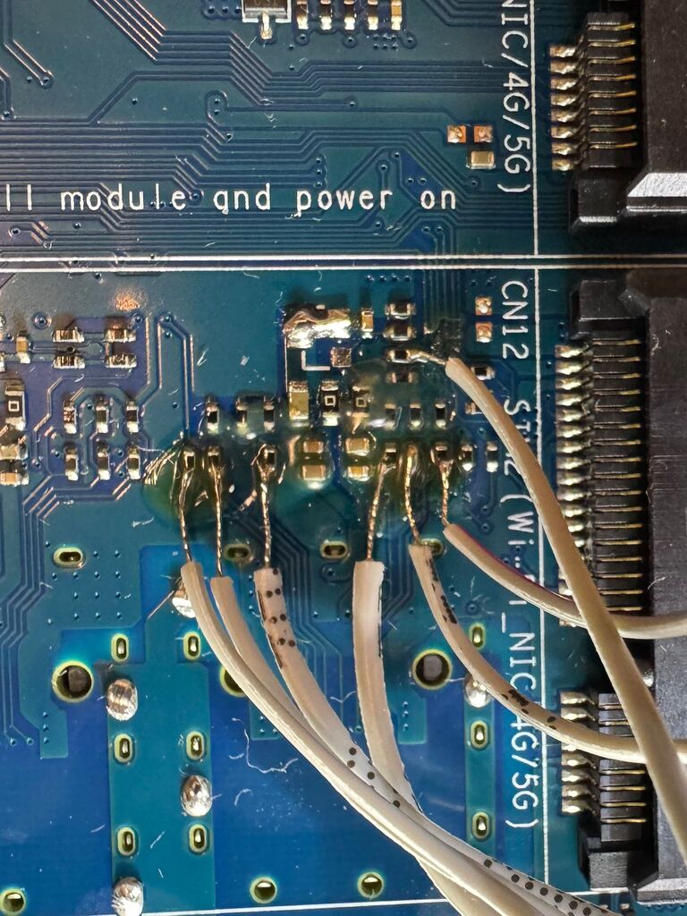
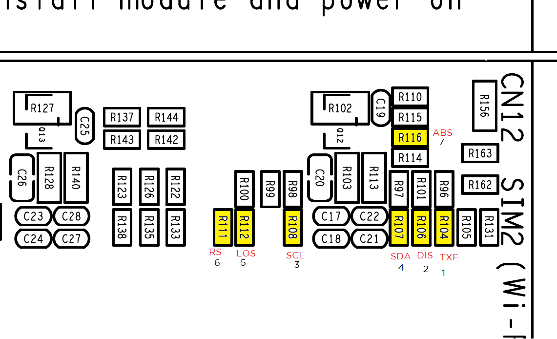
Hi folks, I’ve added a bunch of test leads on my bpi-r4 and traced the s800e startup:
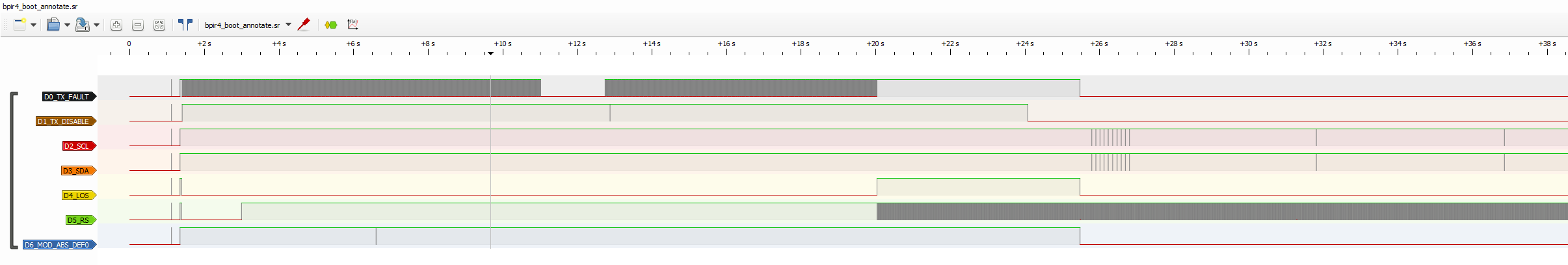
I don’t have any answers, but these are my observations:
- after poweron, LOS, tx-fault and moddef0 goes low after about 25s, which is almost identical to the working mellanox capture. Seems like the S800E starts up as long as there is 3.3V, regardless of tx-disable.
- tx-disable is mostly high during startup, then it goes low at about 24s. This is unexpected to me as I would think that tx-disable will only be toggled after moddef0 state has changed. Also for comparison, tx-disable is almost always held at GND on the mellanox.
- rate select looks like it’s floating and generating a lot of noise, which is probably OK since “floating” is a valid state
- however tx-fault also looks noisy during the first ~20s which is strange because it is supposed to be pulled up to 3v3 via a 4.7K resistor (R96). Maybe it is affected by tx-disable being high?
- after moddef0 goes low, the sfp driver can be seen probing quickly (10x 100ms) then switching to 5s interval probes. All i2c requests are not acknowledged. Eventually it times out with the EEPROM error
- The SCL clock rate looks okay at about 100k, in fact the mellanox i2c runs slightly faster at about 120k.
At the time of capture, the only active hardware modification is the mosfet bypass. The previously removed R106 has been bridged. Pulseview capture here: bpir4_boot_annotate.sr (631.5 KB)
looks like primary difference between the two is that tx-disable is pulled low about 2s into bootup on the mellanox.
as tx-disable is an input on the bpi-r4. question is what is causing S800E to pull tx-disable pin low on mellanox?
tx-disable switches between an input (high impedance) and output:
As far as I can tell, it is enabled once during initialization:
Today in hardware gore, I thought it would be interesting to stick an actual at24 eeprom directly on the bus, using values dumped from the S800E.
The EEPROM gets detected, and the sfp driver halts after detecting a checksum failure. Sure enough, after adding up all the bytes to verify, the original checksum from the S800E is indeed incorrect.
[  182.279685] sfp sfp1: EEPROM base structure checksum failure: 0x98 != 0x5c
[  182.286582] sfp EE: 00000000: 03 04 01 20 00 00 00 00 00 00 00 03 64 00 14 c8  ... ........d...
[  182.295274] sfp EE: 00000010: 00 00 00 00 48 55 41 57 45 49 20 20 20 20 20 20  ....HUAWEI
[  182.303963] sfp EE: 00000020: 20 20 20 20 00 00 00 00 53 38 30 30 45 00 00 00      ....S800E...
[  182.312655] sfp EE: 00000030: 00 00 00 00 00 00 00 00 00 00 00 00 04 f6 00 5c  ...............\
[  182.321342] sfp EE: 00000040: 90 d2 8c 80 01 00 00 00 30 bd d0 80 c0 ff ff ff  ........0.......
[  182.330054] sfp EE: 00000050: 24 35 01 80 c0 ff ff ff 70 bd d0 80 c0 ff ff ff  $5......p.......
I compared the values just in case the dump was wrong. I ran ethtool -m eth0 hex on on the mellanox, and compared with another dump generated from the raw i2c signals, and they both match correctly. At least this can be quirked into the sfp driver, assuming the i2c issue ever finds a solution.
Anyway, base structure and the extended structure both have checksum failures. I used i2csfp to fix them (thank you ericwoud)
root@OpenWrt:/tmp# ./i2csfp sfp1 eepromfix
Checksum 0x00-0x3e failed, set at 5c, but should be 98
Checksum 0x40-0x5e failed, set at 55, but should be f9
Error: i2c_transfer() failed: No such device or address
Error: i2c_transfer() failed: No such device or address
Error: i2c_transfer() failed: No such device or address
Error: i2c_transfer() failed: No such device or address
RollBall Password used: 0xfffffffa
Error: i2c_transfer() failed: No such device or address
Error: Cannot fill in password!

...

root@OpenWrt:/tmp# ./i2csfp sfp1 byte write 0x50 0x3F 0x98
root@OpenWrt:/tmp# ./i2csfp sfp1 byte write 0x50 0x5F 0xF9
root@OpenWrt:/tmp# ./i2csfp sfp1 restore
With the checksums fixed, the module goes further into the initialization!
[  749.594781] sfp sfp1: module removed
[ 1060.452804] sfp sfp1: Host maximum power 3.0W
[ 1060.773374] sfp sfp1: module HUAWEI           S800E rev  sn 4857XXXXXXXXXXXX dc 24082602
[ 1060.803238] hwmon hwmon2: temp1_input not attached to any thermal zone
Strangely, it gets stuck waiting for LOS even though the line was already deasserted:
root@OpenWrt:/tmp# cat /sys/kernel/debug/sfp1/state
Module state: present
Module probe attempts: 0 0
Device state: up
Main state: wait_los
Fault recovery remaining retries: 5
PHY probe remaining retries: 12
Signalling rate: 10313 kBd
Rate select threshold: 0 kBd
moddef0: 1
rx_los: 0
tx_fault: 0
tx_disable: 0
rs0: 0
rs1: 0
Turns out, for some whack reason, the S800E specifies that it requires the LOS to be inverted, so the driver waits indefinitely.
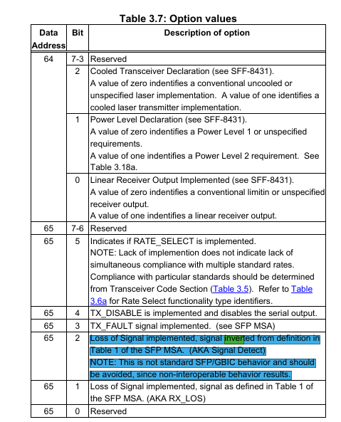
I changed that field from 1C to 1A, wrote it into the EEPROM, and fixed the checksum again:
root@OpenWrt:/tmp# ./i2csfp sfp1 byte write 0x50 0x41 0x1A
root@OpenWrt:/tmp# ./i2csfp sfp1 eepromfix
Checksum 0x00-0x3e matched 98
Checksum 0x40-0x5e failed, set at f9, but should be f7
...
root@OpenWrt:/tmp# ./i2csfp sfp1 byte write 0x50 0x5F 0xF7
root@OpenWrt:/tmp# ./i2csfp sfp1 restore
With that, I was greeted with this:
[  499.274793] mtk_soc_eth 15100000.ethernet eth2: Link is Up - 10Gbps/Full - flow control off
[  499.274823] br-wan: port 2(eth2) entered blocking state
[  499.288355] br-wan: port 2(eth2) entered forwarding state
root@OpenWrt:/tmp# ifconfig
br-lan    Link encap:Ethernet  HWaddr 9A:90:63:9B:8C:BA
          inet addr:192.168.1.1  Bcast:192.168.1.255  Mask:255.255.255.0
          inet6 addr: fe80::9890:63ff:fe9b:8cba/64 Scope:Link
          inet6 addr: fd44:c9c7:ddf::1/60 Scope:Global
          UP BROADCAST RUNNING MULTICAST  MTU:1500  Metric:1
          RX packets:14993 errors:0 dropped:0 overruns:0 frame:0
          TX packets:7007 errors:0 dropped:0 overruns:0 carrier:0
          collisions:0 txqueuelen:1000
          RX bytes:2186957 (2.0 MiB)  TX bytes:2191255 (2.0 MiB)

br-wan    Link encap:Ethernet  HWaddr 9A:90:63:9B:8C:BB
          inet addr:202.XX.XX.XXX  Bcast:202.XX.XX.255  Mask:255.255.255.0
          inet6 addr: fe80::9890:63ff:fe9b:8cbb/64 Scope:Link
          UP BROADCAST RUNNING MULTICAST  MTU:1500  Metric:1
          RX packets:3021 errors:0 dropped:57 overruns:0 frame:0
          TX packets:884 errors:0 dropped:0 overruns:0 carrier:0
          collisions:0 txqueuelen:1000
          RX bytes:286989 (280.2 KiB)  TX bytes:408756 (399.1 KiB)
This permanently “breaks” my sfp1 WAN port, but runs on stock OpenWrt and survives reboots. It’s not a real solution but is very cool to see the link up on a bpi-r4.
Edit: happy new year folks!
Happy New Year to you too… great to see some soldering porn on the 1st day of the year.
the 1st question that pops to mind, since the checksum of S800E is wrong. Wy didn’t the mellanox flag it? which also begs to the importance of the epprom data.
S800E is a SFP+ xgs-pon ONU. So for all intensive purpose, we don’t really care what the eeprom say as long as
kern.info kernel: [ 11.624377] mtk_soc_eth 15100000.ethernet eth2: switched to inband/10gbase-r link mode
so more like a fixed-phy than an sfp. which gave me a really stupid/crazy idea… going to test it out now.
Mellanox (specifically this connectx-3) runs off kmod-mlx4-core and does not appear to involve the current sfp driver that we are hacking on, so the implementation is probably different and possibly more forgiving.
IMO the EEPROM data is “nice to have” but not absolutely necessary. LOS is already exposed as a pin, the only useful omission is the DDMI data such as rx power level, module temperature. Most of the actual link configuration appear to be done in-band once the soc is aware that it is possible to do so.
Going to be fun to see what you are up to, if I had to guess, likely something to do with gmac1 on the devicetree? :^)
crazy/stupid idea worked!
going to test a few more things then clean things up. hotplug(as in plugin and plug out), reboots and cold power on. All works. No hardware hacks needed and only minor dts changes needed.
Details to follow.
Special thanks to @j_g and all who chipped in.
To get the S800E working on bpi-r4 without any hardware modifications on openwrt-24.10. Current mainline may have switched around sfp1/sfp2 and/or gmac/eth definitions. Do your homework before you start.
Step one: Edit mt7988a-bananapi-bpi-r4.dtsi
Remove the following:

	/* SFP1 cage (WAN) */
	sfp1: sfp1 {
		compatible = "sff,sfp";
		i2c-bus = <&i2c_sfp1>;
		los-gpios = <&pio 54 GPIO_ACTIVE_HIGH>;
		mod-def0-gpios = <&pio 82 GPIO_ACTIVE_LOW>;
		tx-disable-gpios = <&pio 70 GPIO_ACTIVE_HIGH>;
		tx-fault-gpios = <&pio 69 GPIO_ACTIVE_HIGH>;
		rate-select0-gpios = <&pio 21 GPIO_ACTIVE_LOW>;
		maximum-power-milliwatt = <3000>;
	};

Edit &gmac2 to the following, must change usxgmill to 10gbase-R and remove sfp reference.

&gmac2 {
	managed = "in-band-status";
	phy-mode = "10gbase-r";
	status = "okay";
};
Step two: Add the following to startup /etc/rc.local to force manually enable power to the S800E in sfp1 slot.
echo 594 > /sys/class/gpio/export
echo out > /sys/class/gpio/gpio594/direction
echo 0 > /sys/class/gpio/gpio594/value
Step three: (optional) Edit eth2 device under /etc/config/network. Adjust to own taste.
config device
        option name 'eth2'
        option autoneg '0'
        option speed '10000'
        option duplex '1'
        option rxpause '1'
        option txpause '1'
In my testing, hotplugging works and link goes up and down. warm restarts sysupgrade and cold boot all work.
One thing to note, the S800E does run warm. So it’s reading 57 deg cel and have been running the last 12+hrs… Up from 50 deg cel without the S800E module. This is with the factory casing (all case up) and a passive heatsink on the processor. And this is also overclocked from 1.8GHz to 2.2GHz at the same default voltage. All within safety margins i suppose.
Have fun and don’t burn down the house.
1 Like
Nice, excellent to see that it is possible to get a working link without any physical mods!
Exciting as the bpi-r4 is probably one of the best performance-to-value option for 10g-capable routing (assuming that the bpi-r4 can concurrently push line rates at both SFP+ ports).
For step two, I wonder if it is possible to move it into the devicetree, something like this:
&pio {
+     sfp1-module-power-hog {
+          gpio-hog;
+          gpios = <&pio 82 GPIO_ACTIVE_HIGH>;
+          output-low;
+     };
     pwm0_pins: pwm0-pins {
          mux {
               groups = "pwm0";
               function = "pwm";
          };
     };
};
If that works, it’ll keep all the changes within the devicetree and might make it easier to maintain a single dtso to hack in support for the S800E.
For step 3, how optional is that configuration? i.e. can I plug in the S800E and expect a working 10g link to come up automatically without touching /etc/config/network?
57 degC should be a reasonably comfortable temperature for the S800E. Assuming the EEPROM values are sane, the temperature should only be a cause for concern above 70c+.
        Module temperature                        : 58.23 degrees C / 136.82 degrees F
        Module temperature high alarm threshold   : 80.00 degrees C / 176.00 degrees F
        Module temperature high warning threshold : 75.00 degrees C / 167.00 degrees F
Will test out your sfp1 moddef0 output low dt changes. The advantage is that dt are applied almost immediately on boot. rc.local happens much much later. So on a cold boot, the connection should come up much faster.
I expect speed and duplex to be negotiated successfully . But flow control will be on auto which will not work for sfp devices i tried previously. And given in my case both sfp are connected to 10G, I rather hardcode it.
No issues pushing line rate for forwarding. As there are 3 ppe engines one each of the gmac. I had previously tested pushing near line rate forwarding between both sfp+ ports on two relatively fast machines with iperf3 --bidir. For traffic terminating at the bpi-r4, rss/lro are not available yet. So I am maxing out at 6.5Gbps+ on iperf3 receive on the device itself.
Also mtk has been active adding patches to the 6.6 kernel and happy days. HQoS was recently added. And from my limited testing it does improve latency on a 10G fiber thou only modestly as latency was pretty low already.
@j_g the above change to DT did not work. builds but system fails to boot up after sysupgrade. strange…
I can’t tell if there is an issue with that entry, but maybe taking one step back would be to try with LEDs instead? Can probably change led_green to use the moddef0 pin instead, and switch it to GPIO_ACTIVE_LOW?
Also curious, in your working hacked devicetree, when the link is up, does anything respond on the i2c bus where the S800E should have been? Still scratching my head on why the S800E doesn’t respond on i2c, but at least we can eliminate some possibilities such as bad power supply, or module held in reset.
still scratching my head on gpio-hog, i double checked seems correct. Maybe someone else can chip in. @ericwoud @frank-w
I left sftp1 i2c intact on device tree. And I just checked. This is with S800E active and link up. Nada… zip… nothing…
i2cdetect -y 3
     0  1  2  3  4  5  6  7  8  9  a  b  c  d  e  f
00:                         -- -- -- -- -- -- -- --
10: -- -- -- -- -- -- -- -- -- -- -- -- -- -- -- --
20: -- -- -- -- -- -- -- -- -- -- -- -- -- -- -- --
30: -- -- -- -- -- -- -- -- -- -- -- -- -- -- -- --
40: -- -- -- -- -- -- -- -- -- -- -- -- -- -- -- --
50: -- -- -- -- -- -- -- -- -- -- -- -- -- -- -- --
60: -- -- -- -- -- -- -- -- -- -- -- -- -- -- -- --
70: UU -- -- -- -- -- -- --
You need to remove the gpio from the sfp part. But with overlay cannot delete. But you can overwrite the gpio of the sfp with an unused one. Then it is free to hog.
Check dmesg log for conflicts
i have deleted the entire sfp1. it is free as i can control it from userspace. Don’t understand what u mean by overlay cannot delete.
I meant with a .dtbo cannot delete from .dtb
question: why active_high instead of active_low? Also does it matter? since it will be set to output-low.
I don’t think the polarity is as critical in gpio-hog, ultimately output-low is what we want to keep the mosfet active:
- output-low  A property specifying to set the GPIO direction as output with
	      the value low.
I picked active_high out of habit, in this context, active_low is semantically better since a p-channel mosfet gate/output is inverting in a high-side switch topology.
However, if you are going to try using leds instead of gpio-hog, GPIO_ACTIVE_LOW will make a difference since it provides the polarity context to default-state = "on";