Is there a Hardware-Engineer at SinoVoip who can explain how the powering of the M2+ in detail works? Can we see a schematic ?
We are having problems to hold the device over a long time on its maximum capabilities.
Is there a Hardware-Engineer at SinoVoip who can explain how the powering of the M2+ in detail works? Can we see a schematic ?
We are having problems to hold the device over a long time on its maximum capabilities.
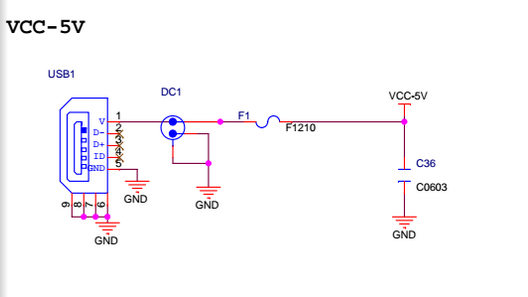
I cannot find DC-Port connection and how it delivers power to H3, can you show me ?
here:
Thank you.
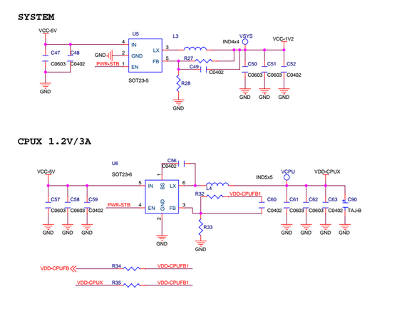
SYSTEM is where the DC-Port (5V, 2A) is connected, right?
What is the name of the Chips: U5 and U6 so I can find Data sheet?
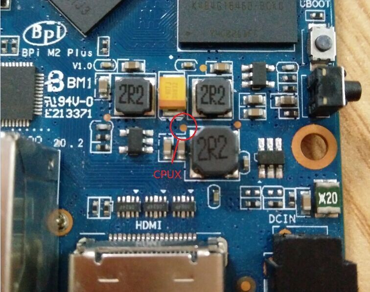
Where is the test point to measure VDD_CPUX please?
U5:SY8089AAAC,U6:SY8113BADC
red LED on Power Supply 5,16 Volt (measured on the PCB, Pin39 to power-barrel) GND attached to Pin 39
as reference Pin 1 = 3,23 V Pin 2 = 5,13 V
According to the schematic it should be 1,20V but I measure 1,30V ? Can you explain, why my results do not fit with your schematics ?
here are my results in the picture: (direct link to picture)
Am also very interested in this mismatch. And there’s another problem. I’ve never seen any of you @sinovoip or Foxconn guys showing a picture of any of your boards with a heatsink on it.
Both M3 and M2+ are prone to heavy overheating. Do you really never test your boards under real world conditions? Do you care about settings like these: https://github.com/BPI-SINOVOIP/BPI-M2P-bsp/blob/ce11facf03efb8cc1b2f84d220e0a371baba9ba1/sunxi-pack/chips/sun8iw7p1/configs/BPI_M2P_720P/sys_config.fex#L414-L418
it is right, it limit from 1.1V to 1.4V, we setting it to 1.3V.
If you don’t care about warranty, you can follow this article. 
https://blog.nyamoe.com/2017/04/how-to-adjust-the-cpu-volt-of-bpi-m2p-banana-pi/