Configuracion y uso de GPIO en Banana pi M2 Zero video y guia completa.
Video de Instalacion y Configuracion.
Video de instalación con script
Guia paso a paso Git.
Configuracion y uso de GPIO en Banana pi M2 Zero video y guia completa.
Video de Instalacion y Configuracion.
Video de instalación con script
Guia paso a paso Git.
Hello congratulations, great job. I followed the procedure step by step while the script was running. At the end of the procedure, unfortunately, I still can’t run the m2z_led.py script.
Always the same error: ################################################################### Unable to determine hardware version. I see: Hardware: Allwinner sun8i Family ,
The libraries seem to me all downloaded, the only thing the board.sh was not created.
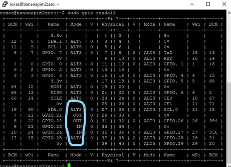
Command line “gpio readall” ok i see the banana pi pinout!
hello and an apology for my not very good english
According to what you tell me, I have reviewed the script and everything seems to work fine, your problem may be about the locations of the files,
As you tell me, the scripts are designed for RPi but with the configuration that was established, everything should work fine for you.
another thing that I tell you that it is not only the execution of the script but you will also have to enable the operation of the gpio pins from armbian-config by entering system and then hardware you will have to select lw-gpio and restart.
the same and done this, your problem has not been corrected, we recommend that you review my git repo in detail since I have the manual and automatic installation.
And finally, and even so it doesn’t work for you, I’ll be uploading a new video to my YouTube channel with the update on how to install, but now through the script.
note: if you used the auto-install script, remember that you should run it as root and when selecting the directory you should specify your home directory, not root.
and anything you need you can comment on it and I will try to answer as quickly as possible.
hello tried today but to no avail.
I still get tab error: root@bananapim2zero:/home/pi/Banana-pi-m2-zero-GPIO# sudo python3 m2z_led.py Traceback (most recent call last): File “m2z_led.py”, line 4, in import RPi.GPIO as GPIO File “/usr/local/lib/python3.8/dist-packages/RPi/GPIO/init.py”, line 23, in from RPi._GPIO import * RuntimeError: This module can only be run on a Raspberry Pi!
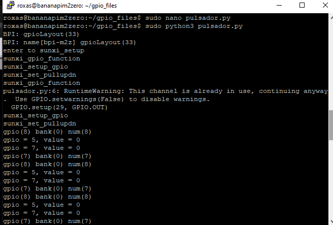
Hi I did a new clean reinstall with scripts, now m2z_led.py runs Ok! But does not read in INPUT any change of State from Low = 0 to High = 1 when I connect the cables (GPIO.input) Physical Pins Used 37 and 39 (GND)
Of course, my friend, what happens is that after you told me that it didn’t work, I started to rewrite the script so that it could give support to the pins again, in addition to making a new video where I explain the installation and use of the scripts in more detail.
Also for your question about the output of pin 37, you will have to check carefully which pin you are using since the banana pi has a double modular pin that turns out to be 37 in this case.
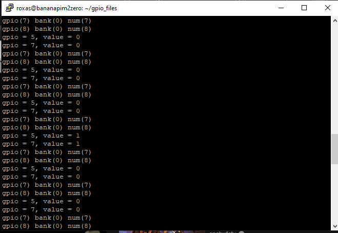
hello here is my readall but in my opinion it is not the actual one on the bpi board, pin connected to 37 and 39 (GND) but it reads random values 1,0. It does not read any event status changes when I join the 2 wires together. On the raspberry it works beautifully, when I join the GPIO.input wires it goes from 1 to 0. In my opinion the readall pinout is wrong, is it possible to map the pins on the board bpi in a forced way (command)?
I write last image but it seems not to boot correctly on banana pi COM3 - Serial Connection
look reviewing this as you mention there is a small problem but it is normal since when writing the RPi table for the banana pi it is very old what I did was about writing the compilation of this for the raspberry pi zero even though I knew that this would bring I solved some problems by reloading the python dependencies load to .3 seconds to avoid the challenge of changing the dependencies table and pin configuration
Apart from answering your question about whether there is a way to change the pins with commands, it worked out for me, you use /sys/class
In what you tell me about the image that is failing, I think it could be due to the compression system that I use since one part affects the use of serial ports, even though I did not think that it would affect when saving the image to the SD.
I am telling you this because what I did was remap the partitions so that it could be used with any SD capacity, since when I share an image that is already ready it usually weighs 30GB and with the method of compression and remapping of the sectors I can do that from those 30GB go to 1GB already compressed but if you want to try with a minimal image you could do it with the minimal server image or with the arch linux one that is also in one of my git repositories and if you are interested in arch there is also the possibility to use the GPIO pins even though the python RPi method changes a bit since we do not make a direct call to the libraries but we attach the moludo that we need on the fly.
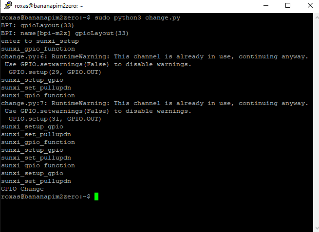
look friend I already made a few more changes to the script and from what I understood you could not read entries in this new version of the script I recommend that you install it clean since it adds and modifies certain things in addition to now adding a new example of a button and a led for examples of digital pin readings and apart from that I will include some methods to change the state of the pins, as well as write and read the pins.
change pin mode: gpio -g mode (Pin_Number) (Status: in or out)
write pin status: gpio -g write (Number_of_Pin) (Mode: 1 or 0)
read pin status: gpio -g read (Pin_Number)
enable or disable pull-up resistor: gpio -g mode (Pin_Number) (Mode: up or down)
 !
!
 !
!
Hello reinstalled the script, button connected to 2 wires: wire 1 = Physical Pin 31, wire 2 = physical Pin 39 (GND)
M2z_button_state.py script keeps reading RANDOM HIGHT, LOW values , no Event change value read in GPIO.input when I join the 2 wires… On rpi-Zero I read GPIO.input status change from 1 to 0 Would it be possible to force change pin mapping on the command?
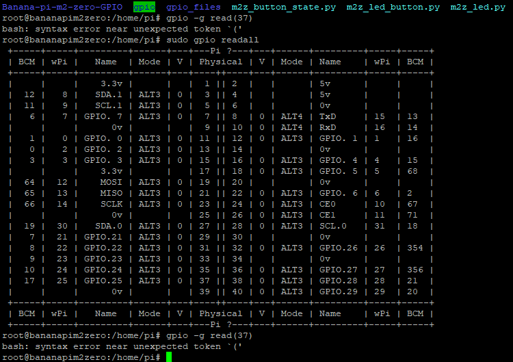
hi these commands, are they camandi bash?
gpio -g read (37)
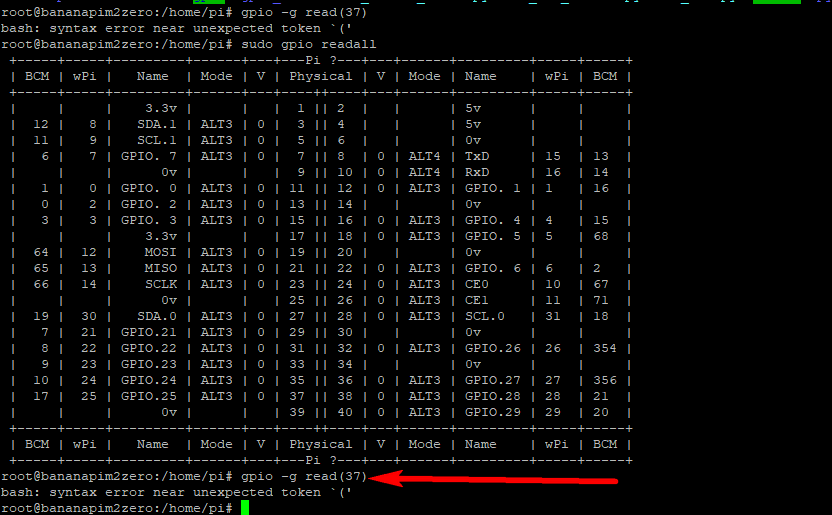
From checks also pins 8 and 10 (UART3) are inverted compared to what readall says, the Real Pins on the board are actually 8 = Rx and 10 = Tx.
How can they force the mapping change?
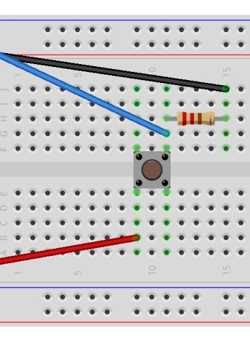
ok I think I understand what is happening look I think the problem you have is not the script but that you are not connecting your button correctly.
Here I leave you how you should connect it, being the blue cable the pin that you are going to occupy the black GND and the red 5V, you will also need a 10K resistor
Ok It works! thanks.
Why is resistance needed here? How to make a way to go without resistance? On raspberry pi zero no resistor is required, I connect GND to Pin37 it was change from 1 to 0.
As I remember it was because the raspberry boards have a pull down set and the banana pi only uses it on some pins.
if you don’t want to use a resistor you could pull-up the pin but it will always be high.
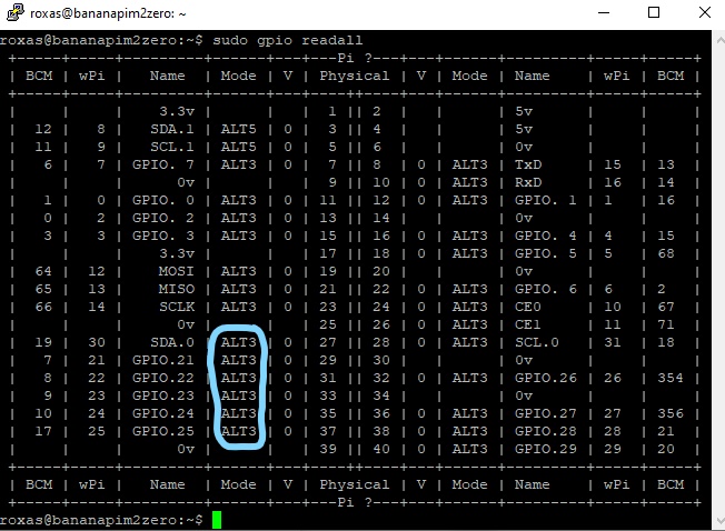
Direct Set PullDown on which pins would be available on banana pi board?
For the board pin mapping change which command should I use. Important the remap UART3: pin8 bring it back to TX and pin 10 to RX as in rpi zero.
no friend, in fact the RX and TX pins are fine I have been testing them and I have not had problems with them, and the truth is that I do not remember the pull-down pins very well but I think that 15 and 16 are in pull-down and for the pin command is without parentheses.
example: sudo gpio -g read 29
or another way to change the state of the pins is with a python script, also if you want to check if the pin is pull-down you can use the following command to declare the pin as pull-down or pull-up, just one thing the pull-up is almost only for output
GPIO.setup(31, GPIO.IN, pull_up_down=GPIO.PUD_DOWN)
GPIO.setup(31, GPIO.IN, pull_up_down=GPIO.PUD_UP)
hello I started trying RPi.GPIO libraries but callback functions also don’t work:
Python Code not work:
GPIO.add_event_detect(pin, GPIO.BOTH, call back=myFunction)
) GPIO.add_event_detect(pin, GPIO.FALLING, call back=myFunction)
Error Code: RuntimeError: Failed to add edge detection
No use Resistor: To avoid using resistance I have tried to set pull down on pin 31 but GPIO.input still reads random values, if I put 10k resistor it works instead.