[BPI-R64] PWM-support

Checked that already. dmesg is quite clean w.r.t. pinctrl:

> dmesg|grep pinctrl
[    0.086542] pinctrl core: initialized pinctrl subsystem

I also checked debugfs

> cat /sys/kernel/debug/pwm 
platform/11006000.pwm, 6 PWM devices
 pwm-0   (sysfs               ): requested period: 0 ns duty: 0 ns polarity: normal
 pwm-1   ((null)              ): period: 0 ns duty: 0 ns polarity: normal
 pwm-2   (sysfs               ): requested enabled period: 40000000 ns duty: 400000 ns polarity: normal
 pwm-3   ((null)              ): period: 0 ns duty: 0 ns polarity: normal
 pwm-4   ((null)              ): period: 0 ns duty: 0 ns polarity: normal
 pwm-5   ((null)              ): period: 0 ns duty: 0 ns polarity: normal

Looks as expected. I used different values for period and duty_cycle than in earlier messages. But the above matches what I used on the command line.

> btw. echo 0 is basicly wrong…echo “1” creates pwm0

I found there are some different between Kamble’s layout and BPIR64 ?
It should be the following setting in the dts of bpir64

static int mt7622_pwm_ch1_0_pins[] = { 51, };
static int mt7622_pwm_ch2_0_pins[] = { 52, };

	pwm_pins: pwm-pins {
		mux {
			function = "pwm";
			groups = "pwm_ch1_0", /* mt7622_pwm_ch1_0_pins[] = { 51, }; */
				 "pwm_ch2_0", /* mt7622_pwm_ch2_0_pins[] = { 52, }; */

		};
	};

echo “0” > export not working ?
It shoud create pwm0 node after this command, and this mapping to PWM1 on the “GPIO51/TXD2/PWM_CH1”

@frank-w The LED should have 50% brightness with the follow setting

root@bpi-r64:/sys/class/pwm/pwmchip0/pwm0# echo 10000 > period
root@bpi-r64:/sys/class/pwm/pwmchip0/pwm0# echo 5000 > duty_cycle 
root@bpi-r64:/sys/class/pwm/pwmchip0/pwm0# echo 1 > enable

If i read sheme right pwms 4,5,6 are also wrong (gpio 67,68,69).

I will try the other gpios…

Do i need your patch i linked above?

Should apply patch If you want to see the LED real blinking,
But without this patch we can still see different brightness
(Blinking too quickly for human eye) of LED
when changing duty_cycle.

thank you i wil try it out…with changed pwm0 pins it works

also tried again with ‘echo “0” > export’ creates pwm0 node…don’t know why last time comes error and 1 creates 0-node

root@bpi-r64:/sys/class/pwm/pwmchip0/pwm0# echo 10000 > period                  
root@bpi-r64:/sys/class/pwm/pwmchip0/pwm0# echo 5000 > duty_cycle     #half brightness
root@bpi-r64:/sys/class/pwm/pwmchip0/pwm0# echo 1 > enable                      
root@bpi-r64:/sys/class/pwm/pwmchip0/pwm0# echo 1000 > duty_cycle    #darker ~ 1/10

so i have now these definitions:

    pwm_pins: pwm-pins {
            mux {
                    function = "pwm";
                    groups = "pwm_ch1_0", /* mt7622_pwm_ch1_0_pins[] = { 51, }; */
                             "pwm_ch2_0", /* mt7622_pwm_ch2_0_pins[] = { 52, }; */
                             "pwm_ch3_2", /* mt7622_pwm_ch3_2_pins[] = { 97, }; */
                             "pwm_ch4_1", /* mt7622_pwm_ch4_1_pins[] = { 67, }; */
                             "pwm_ch5_0", /* mt7622_pwm_ch5_0_pins[] = { 68, }; */
                             "pwm_ch6_0", /* mt7622_pwm_ch6_0_pins[] = { 69, }; */
                             "pwm_ch7_2"; /* mt7622_pwm_ch7_2_pins[] = { 101, }; */
            };
    };

@sam33, I see that the GPIO pinout image you posted is the one from http://wiki.banana-pi.org/Banana_Pi_BPI-R64. And I am using the schematics posted in the Documents section:

They are indeed different. Eg. CON2 pin 7 appears to be connected to GPIO101 in the image, but to GPIO95 in the schematic PDF. So I don’t know which one is the correct version.

In any case, for FAN_OUT, it is shown only in the schematic PDF file. So that is the only source of information.

How do we get in touch with BPI team to get authoritative info? Is it by including this: @sinovoip

tested with my led on fan-socket, good message: it responds, while pwm is disabled i see LED lightening with full brightness. if i activate pwm with this code:

root@bpi-r64:/sys/class/pwm/pwmchip0/pwm2# echo 10000 > period
root@bpi-r64:/sys/class/pwm/pwmchip0/pwm2# echo 5000 > duty_cycle
root@bpi-r64:/sys/class/pwm/pwmchip0/pwm2# echo 1 > enable

led goes off, also with duty_cycle of 8000 it stays off, if i disable pwm with echo 0 > enable, LED goes on again (no errors on console or hints in dmesg)

pushed current code to 5.7-pwm branch

as for blinking-patch, can we decide from userspace between blinking and darker appearence? as some users want darker LED and others want flashing. I thought this is done via period/duty_cycle…small period makes higher frequency…so the darker appearance without flicker. If i want blinking period has to be longer

I too had success with a real fan in the fan socket. I tried the same technique as you @frank-w – using an LED in the FAN socket. Noticed that the LED was full on when the PWM was not enabled (echo 0 > enable), and was responding with varying level of brightness as I changed the period and duty cycle. So effectively, the FAN_OUT control was behaving in a reverse polarity. So for now, with the fan connected, I have set the period to 2000000 (2M), and when the duty cycle is very low (say 40000 (0.04M)), the fan runs at high speed, and when duty cycle is say 1500000 (1.5M) it runs at low speed (and of course less noise).

I’ll play around with the polarity and see if I can use the duty cycle as ON time rather than OFF time.

BTW, I am maintaining the groups to

groups = "pwm_ch1_2", "pwm_ch2_2", "pwm_ch3_2", "pwm_ch4_3", "pwm_ch5_2", "pwm_ch6_3";

in the DTS, because I want to keep GPIOs 95…100 as PWM which needs pin func to be 0.

Thanks all for the support.

So pwm is active if deactivated but with reversed polarity (duty_cycle defines off-time instead of on-time)?

Why using old pwm definitions if they mapped on other gpios? Do they respond to your changes on same external pins? Bit confusing…

I understand the circuit behavior of FAN_OUT control and hope that this post resolves your confusion @frank-w

From the schematics I posted in #17 above, we can see that Q33 acts as a logic inverter driving Q40. So when FAN_OUT is low, Q33 is OFF, which make gate of Q40 high and turns Q40 ON so that full power is delivered to the fan connector (CN19). When FAN_OUT is high, Q33 is ON which in turn turns OFF Q40 and cuts off power to the fan. That is why when we disable the PWM through echo 0 > enable, the fan runs at full speed. And when we have a high duty cycle (~90%), the fan turns on only 10% of time and thus runs slow.

I tried changing the polarity of PWM3 (ie. FAN_OUT), but get a ENOTSUPP (error value 524)

/sys/class/pwm/pwmchip0/pwm2# echo "inversed" > polarity 
-bash: echo: write error: Unknown error 524

It turns out that in drivers/pwm/core.c, pwm_apply_state() returns ENOTSUPP if chip->ops->set_polarity is not defined. This is the case for the mediatek driver drivers/pwm/pwm-mediatek.c. It has only the following ops defined:

static const struct pwm_ops pwm_mediatek_ops = {
        .config = pwm_mediatek_config,
        .enable = pwm_mediatek_enable,
        .disable = pwm_mediatek_disable,
        .owner = THIS_MODULE,
};

If we grep set_polarity drivers/pwm/*, many other boards have a function to set the polarity to either "normal" or "inversed". So I need to file a bug/feature request or create a PR to include support for changing PWM polarity for mediatek pwm driver.

1 Like

tried again with pwm2 (fan-socket), but i do not recognize any change in brightness…

root@bpi-r64:/sys/class/pwm/pwmchip0/pwm2# echo 10000 > period                  
root@bpi-r64:/sys/class/pwm/pwmchip0/pwm2# echo 5000 > duty_cycle
root@bpi-r64:/sys/class/pwm/pwmchip0/pwm2# echo 1000 > duty_cycle        
root@bpi-r64:/sys/class/pwm/pwmchip0/pwm2# echo 8000 > duty_cycle

only if i change enable to 1, led goes off

@Mbk_Kamble which kernel do you use? i’m using the 5.7-pwm branch

as far as i looked into other pwm drivers, the function for inverting is basicly same

static int vt8500_pwm_set_polarity(struct pwm_chip *chip,
                                   struct pwm_device *pwm,
                                   enum pwm_polarity polarity)
{
        struct vt8500_chip *vt8500 = to_vt8500_chip(chip);
        u32 val;

        val = readl(vt8500->base + REG_CTRL(pwm->hwpwm));

        if (polarity == PWM_POLARITY_INVERSED)
                val |= CTRL_INVERT;
        else
                val &= ~CTRL_INVERT;

        writel(val, vt8500->base + REG_CTRL(pwm->hwpwm));
        pwm_busy_wait(vt8500, pwm->hwpwm, STATUS_CTRL_UPDATE);

        return 0;
}


static int ecap_pwm_set_polarity(struct pwm_chip *chip, struct pwm_device *pwm,
                                 enum pwm_polarity polarity)
{
        struct ecap_pwm_chip *pc = to_ecap_pwm_chip(chip);
        u16 value;

        pm_runtime_get_sync(pc->chip.dev);

        value = readw(pc->mmio_base + ECCTL2);

        if (polarity == PWM_POLARITY_INVERSED)
                /* Duty cycle defines LOW period of PWM */
                value |= ECCTL2_APWM_POL_LOW;
        else
                /* Duty cycle defines HIGH period of PWM */
                value &= ~ECCTL2_APWM_POL_LOW;

        writew(value, pc->mmio_base + ECCTL2);

        pm_runtime_put_sync(pc->chip.dev);

        return 0;
}

i tried to find a mtk-specific value for inverting the polarity (mt7622 datasheet), but found none. basicly we can do similar by modifying the duty-cycle value before writing to register (or write again). something like duty_cycle=period - duty_cycle :wink: but this inverts not the enable-state of course…so still confusing

maybe i’ve found something on Page 527…

110061CC PWM_LOOP_BACK_TEST (lower 5 bits named PWMx_STATUS) for pwm0-4 (not 5&6)

0 PWMx Output is low
1 PWMx Output is high

@sam33 any idea of reversing/fan socket? I wonder why @Mbk_Kamble had success on changing speed of fan and i see no change on modifying duty_cycle in both directions

i verified pwm0-5 (1-6) are working except pwm2 (3=fan because inversion) and pwm6 (7) on bpi-r64 with my current pin-definition (5.7-pwm branch)

root@bpi-r64:~# cd /sys/class/pwm/pwmchip0
root@bpi-r64:/sys/class/pwm/pwmchip0# echo 0 > export
root@bpi-r64:/sys/class/pwm/pwmchip0# cd pwm0
root@bpi-r64:/sys/class/pwm/pwmchip0/pwm0# echo 10000 > period
root@bpi-r64:/sys/class/pwm/pwmchip0/pwm0# echo 5000 > duty_cycle
root@bpi-r64:/sys/class/pwm/pwmchip0/pwm0# echo 1 > enable
  • led on pwm3 is on if disabled and off if pwm is enabled, but i see no brightness difference
  • led on pwm7 does not do anything (gpio-header pin 7/gpio101)…i can export/set values, but no change to led…

@sam33 any idea? @moore wrote above that there is no pwm7 (pwm6 in linux) on mt7622…is this right? that means that all pinctrl mapping pwm7 are wrong…how about the inversion on fan-socket?

mt7622-datasheet i have lists only pwm0-4 (so here i have 1 more working as in the datasheet)

do you plan v3 of your " add longer period support"-patch based on comments on v2?

I checked linux PWM1 (the one on pin 15) with

root@OpenWrt:/sys/devices/platform/11006000.pwm/pwm/pwmchip0/pwm1# echo 1000000 > period root@OpenWrt:/sys/devices/platform/11006000.pwm/pwm/pwmchip0/pwm1# echo 500000 > duty_cycle

and something is really not right.

Falling edge should not looks like that. It should be square wave. It looks like wrong gpio configuration

Similar is on FAN

have you tried smaller period (see sams patch)? i tested only bridghtness of led changing with different values of duty_cycle…have no oscilloscope right here

I had Sam’s patch. Yes smaller period set pin to high. No waveforms

Can you try with my values and without sams patch? Maybe this breaks waveforms

You have added gpio-define like i did?

Maybe gnd is not connected well? You can try another

btw. i have updated my bpi-r64/gpio page to include pwm information:

https://wiki.fw-web.de/doku.php?id=en:bpi-r64:gpio#pwm

Yes, PWM7: GPIO101 is a typo. there is no pwm feature at this pin.

ok, thank you, so mainline dts is also wrong and seans patch useless…or does pwm7 basicly exists on other mt7622 boards? if not also pinctrl is wrong. or is only another gpio used here (and so other pinctrl-definition)?

https://git.kernel.org/pub/scm/linux/kernel/git/stable/linux.git/tree/drivers/pinctrl/mediatek/pinctrl-mt7622.c?h=linux-5.4.y#n442

says pwm7 is available on mt7622 on gpio 70,82 or 101

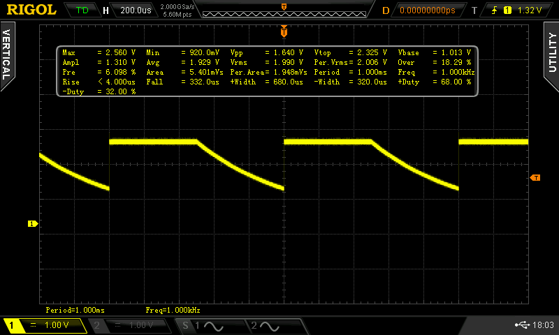
any idea about pwm3 (inversion and not working in my tests)?

I found inversion code for mt8173…maybe this is similar to mt7622

https://android.googlesource.com/kernel/mediatek/+/android-mtk-3.18/drivers/misc/mediatek/pwm/mt8173/mt_pwm_hal.c#514

Register is defined here as offset to pwm-base: https://android.googlesource.com/kernel/mediatek/+/android-mtk-3.18/drivers/misc/mediatek/pwm/mt8173/include/mach/mt_pwm_prv.h#35

In mt7622document there is a clk_pwm_inv as bit 4 in clk_cfg_1 (page 17),but this seems to be for all pwm

@moore Btw. From mt7622 datasheet

I think i’ve found it…on page 528

3dclm

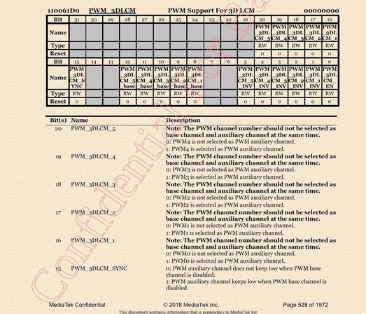
based on enable (11006000 on mt7622) (where pwm_num is a bit too - not like the pwmX-registers PWMx_*)

    value = readl(pc->regs);
    value |= BIT(pwm->hwpwm);
    writel(value, pc->regs);

imho we need to do something like this:

    value = readl(pc->regs + 0x1d0);
    value |= BIT(pwm_no +16); // set aux bit for pwmX
    writel(value, pc->regs); //write aux-bit

    value |= BIT(pwm_no); // set inv bit for pwmX
    writel(value, pc->regs); //write inv bit

for disabling we can use “value &= ~BIT(…);”

but i do not know if the offset (0x1d0) is same on other mtk-socs, so we need to define soc-depended const and choose which to use based on current soc

maybe we can set both bits at same time

diff --git a/drivers/pwm/pwm-mediatek.c b/drivers/pwm/pwm-mediatek.c
index d2efc47655a0..ba0db66bc5e9 100644
--- a/drivers/pwm/pwm-mediatek.c
+++ b/drivers/pwm/pwm-mediatek.c
@@ -197,10 +197,30 @@ static void pwm_mediatek_disable(struct pwm_chip *chip, struct pwm_device *pwm)
        pwm_mediatek_clk_disable(chip, pwm);
 }
 
+static int pwm_mediatek_set_polarity(struct pwm_chip *chip,
+                                    struct pwm_device *pwm,
+                                    enum pwm_polarity polarity)
+{
+        struct pwm_mediatek_chip *pc = to_pwm_mediatek_chip(chip);
+        u32 val;
+
+        val = readl(pc->regs + 0x1d0);//3DLCM register
+
+        if (polarity == PWM_POLARITY_INVERSED)
+                val |= (BIT(pwm->hwpwm + 16) | BIT(pwm->hwpwm));
+        else
+                val &= ~(BIT(pwm->hwpwm + 16) | BIT(pwm->hwpwm));
+
+        writel(val, pc->regs + 0x1d0);
+
+        return 0;
+}
+
 static const struct pwm_ops pwm_mediatek_ops = {
        .config = pwm_mediatek_config,
        .enable = pwm_mediatek_enable,
        .disable = pwm_mediatek_disable,
+       .set_polarity = pwm_mediatek_set_polarity,
        .owner = THIS_MODULE,
 };

android code sets first the aux-bit/enable so maybe it’s better to do this separately…in the docs there are base bits (offset +8) that should not be set if aux-bits (+16) set.

i created new function to set/clear bits in the 3dclm register and call it from the set_inversion function 3 times to set all 3 bit positions (hope i made no mistake).

https://github.com/frank-w/BPI-R2-4.14/commits/5.7-pwm

now we have to define inversion in dts…

i have found this: https://www.kernel.org/doc/Documentation/devicetree/bindings/pwm/pwm.txt

so we need to do something like this, right?

pwm: pwm {
	#pwm-cells = <2>;
};
fan: fan {
	pwms = <&pwm 2 5000000 PWM_POLARITY_INVERTED>;
	pwm-names = "fan";
};

but imho the driver needs to pick the right parameter as inversion…is this same across drivers? maybe we can skip the default period and only pass inversion mode for the pwm (not changing pwm-cells).

i can compile dtb without the 500000, how to tell driver which value is the inversion one?

diff --git a/arch/arm64/boot/dts/mediatek/mt7622-bananapi-bpi-r64.dts b/arch/arm
64/boot/dts/mediatek/mt7622-bananapi-bpi-r64.dts
index ef92ec7921dc..2ea1ddb3716b 100644
--- a/arch/arm64/boot/dts/mediatek/mt7622-bananapi-bpi-r64.dts
+++ b/arch/arm64/boot/dts/mediatek/mt7622-bananapi-bpi-r64.dts
@@ -8,6 +8,7 @@
 /dts-v1/;
 #include <dt-bindings/input/input.h>
 #include <dt-bindings/gpio/gpio.h>
+#include <dt-bindings/pwm/pwm.h>
 
 #include "mt7622.dtsi"
 #include "mt6380.dtsi"
@@ -427,6 +428,11 @@ mux {
                };
        };
 
+       fan: fan-pwm {
+               pwms = <&pwm 2 PWM_POLARITY_INVERTED>;
+               pwm-names = "fan";
+       };
+
        wled_pins: wled-pins {
                mux {
                        function = "led";
diff --git a/arch/arm64/boot/dts/mediatek/mt7622.dtsi b/arch/arm64/boot/dts/mediatek/mt7622.dtsi
index 15b46c742f93..5b59f9b98caa 100644
--- a/arch/arm64/boot/dts/mediatek/mt7622.dtsi
+++ b/arch/arm64/boot/dts/mediatek/mt7622.dtsi
@@ -440,6 +440,7 @@ pwm: pwm@11006000 {
                         <&pericfg CLK_PERI_PWM7_PD>;
                clock-names = "top", "main", "pwm1", "pwm2", "pwm3", "pwm4",
                              "pwm5", "pwm6", "pwm7";
+               #pwm-cells=<2>;
                status = "disabled";
        };

mhm, it looks like the inversion is parsed by pwm/core.c and first param after pwm_no is always the period

https://git.kernel.org/pub/scm/linux/kernel/git/stable/linux.git/tree/drivers/pwm/core.c?h=linux-5.4.y#n146

According datasheet there is “old PWM mode” and linux driver is using it as it set bit 15 of control reg. There is no information what is the difference between old mode and tegular one.

Android driver when setting “old mode” is using different sets of registers.

With untouched pwm driver Pwm-fan is working but opposite: higher values lowered fan speed. But my concern is waveform on real pin.

Can someone with oscilloscope confirm real square waveform on pwm pins?

moved my fan-definition to main block {…}; and made pwm-cells=<3> because of dtc warning…but my set_polarity function isn’t called…any idea?

added debug-message on top of my 5.7-pwm branch

--- a/drivers/pwm/pwm-mediatek.c
+++ b/drivers/pwm/pwm-mediatek.c
@@ -219,6 +219,8 @@ static int pwm_mediatek_set_polarity(struct pwm_chip *chip,
                                     enum pwm_polarity polarity)
 {
        bool inv=(polarity == PWM_POLARITY_INVERSED);
+
+       printk(KERN_ALERT "DEBUG: Passed %s %d PWM#%d, inv:%d\n",__FUNCTION__,__LINE__,pwm->hwpwm,(int)inv);
        //disable base mode for pwm_no

the of_pwm_xlate_with_flags (at least part handling the polarity) is not called, too

addded

pc->chip.of_xlate = of_pwm_xlate_with_flags;

in probe, like it’s done by other drivers, but the function is not called…added some more debug in pwm-core (pwm_get), but it seems no function there gets called. tried also moving the pwms-option to the &pwm-node…but also no success…checked state in apply-callback, but inverted is never set…

[   80.355411] DEBUG: Passed pwm_mediatek_apply 243 PWM#2, inv:0==1?

i found out that there is a pwm-fan driver ./drivers/hwmon/pwm-fan.c (CONFIG_SENSORS_PWM_FAN) which sets pwm by cooling-levels

so maybe we can use it like this:

    fan0: pwm-fan {
            compatible = "pwm-fan";
            pwms = <&pwm 2 10000 PWM_POLARITY_INVERTED>;
            pwm-names = "fan";
            #cooling-cells = <2>;
            cooling-levels = <0 130 170 230>;
    };

but it seems to rely on pwm driver-handling of PWM_POLARITY_INVERTED which is currently broken in mtk driver