Did you make any change to get -89dBm noise level? I’m getting far worse (-75dBm)
1 Like
I’m not using BPI antenna, I’m using the Taoglas antennas
1 Like
Channel selection can also make huge difference.
1 Like
BTW, if you look on any bpi products, none seem to have any RF shielding - not even the OpenWrt One or bpi-r3 (although they seem to have a heatsink at a relatively good place and will probably cover most chips) - but would be interesting to know if bpi-r3 or OpenWrt One might have similar noise levels?
1 Like
It would be great if someone knowledgeable could experiment with rf-shielding. I think the range is decent but it’s the noise that seems to be killing SNR.
1 Like
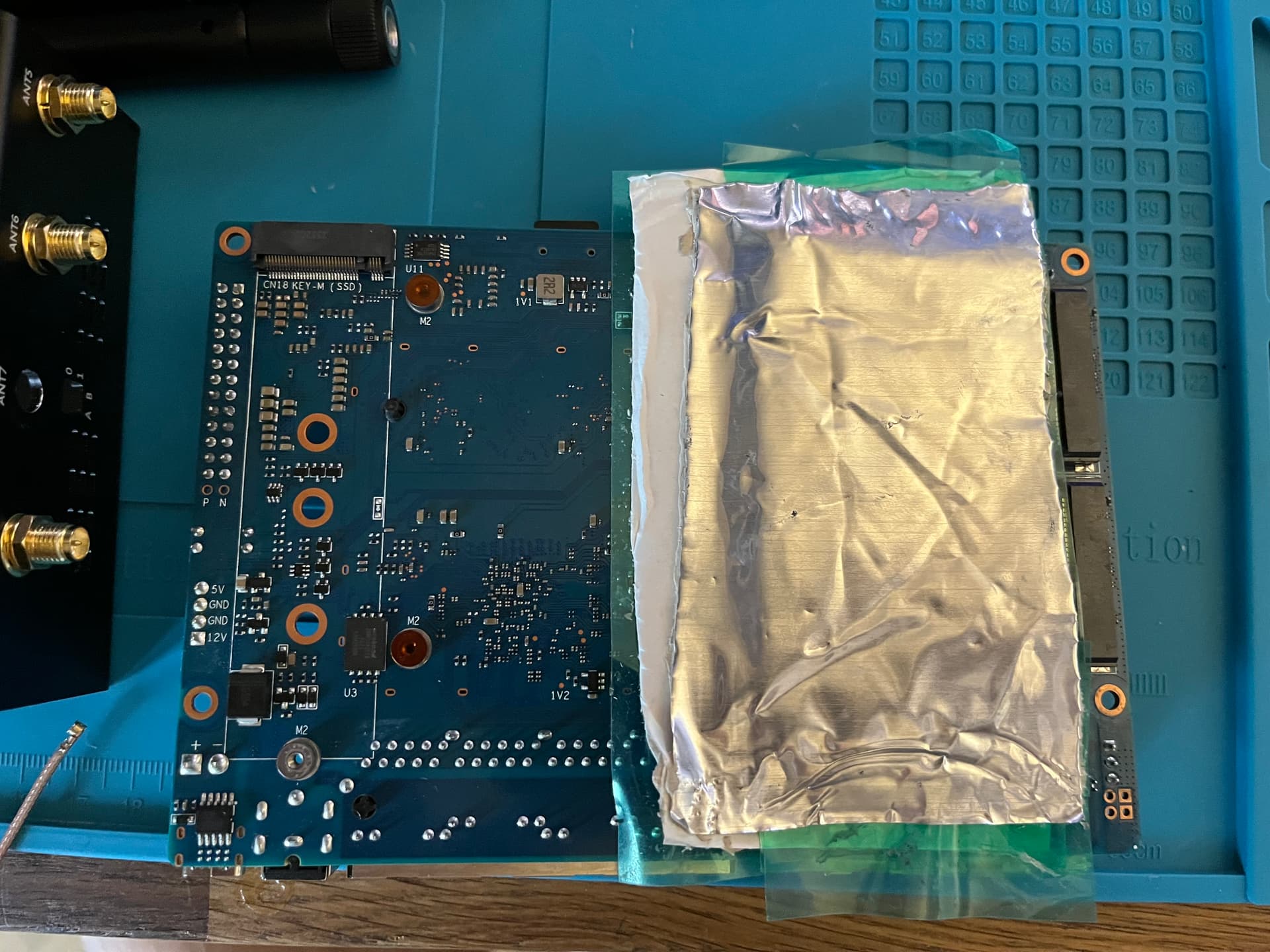
So, I did some experimentation. To make an RF shield I used a piece of aluminum window flashing which has a thick adhesive layer that made it easy to shape around the Wi-Fi board (front and back side) leaving only small gaps for pigtails to pass through. Needless to say, I had the PCBs throughly insulated with high-density sticky tape. The shield was then connected by an alligator lead to the barrel of one of the SMA antenna sockets to provide ground.
Here’s the results. 5 GHz band, channel 132, 80 MHz. The client was a 2021 MacBook Pro, which had the most problems with the BPI-R4 out of all my devices. Distance of ~5 meters to the router, line of sight partially obscured by a concrete wall.
Baseline (stock BPI-R4 housing, no shielding): -65/-71 dB, ~100 Mbps throughput
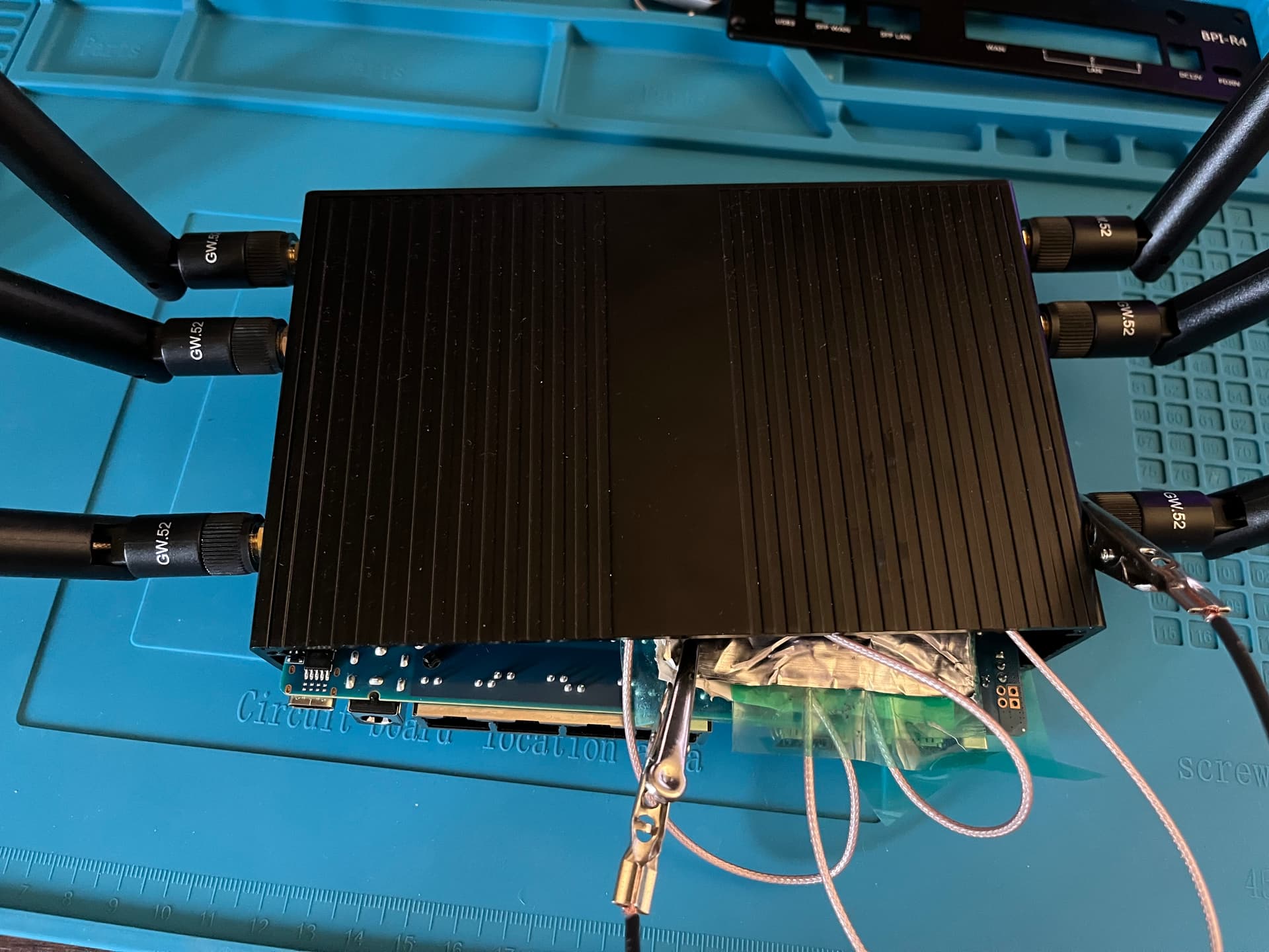
RF shield added, the board is out of the housing: -65/-80 dB, didn’t check throughput
RF shield added, the board partially inserted into the housing (see picture): -65/-85 dB, 300+ Mbps throughput
I have to admit the old Archer C7 still has vastly better noise level at -107 dB. But my ghetto shield was far from perfect as shown by the difference the metal housing made, which provides some shielding of its own from external RF sources. As a general rule, it’s OK to have holes in shielding, but long slot-shaped gaps will allow the radio waves to leak through, that’s why the shield has to sit tight against the PCB. Mine clearly didn’t.
Still, there we have it. The BE14 was indeed hamstrung by the missing RF shield. I took measurements of the board and will come up later with dimensions and mounting system for a proper implementation.
P.S. This was an experiment with the sample size of 1. More people are welcome to try what I did and verify my findings. Just, for the love of God, do your best not to fry the board by short-circuiting something with metal foil.
3 Likes
Here’s the dimensions of RF shields for the front and back side of the board (yes, they are slightly different) assuming thickness of 0.2 mm, which is common and sufficient. 2 mm of inside height will be enough to clear the tallest components on the front side.
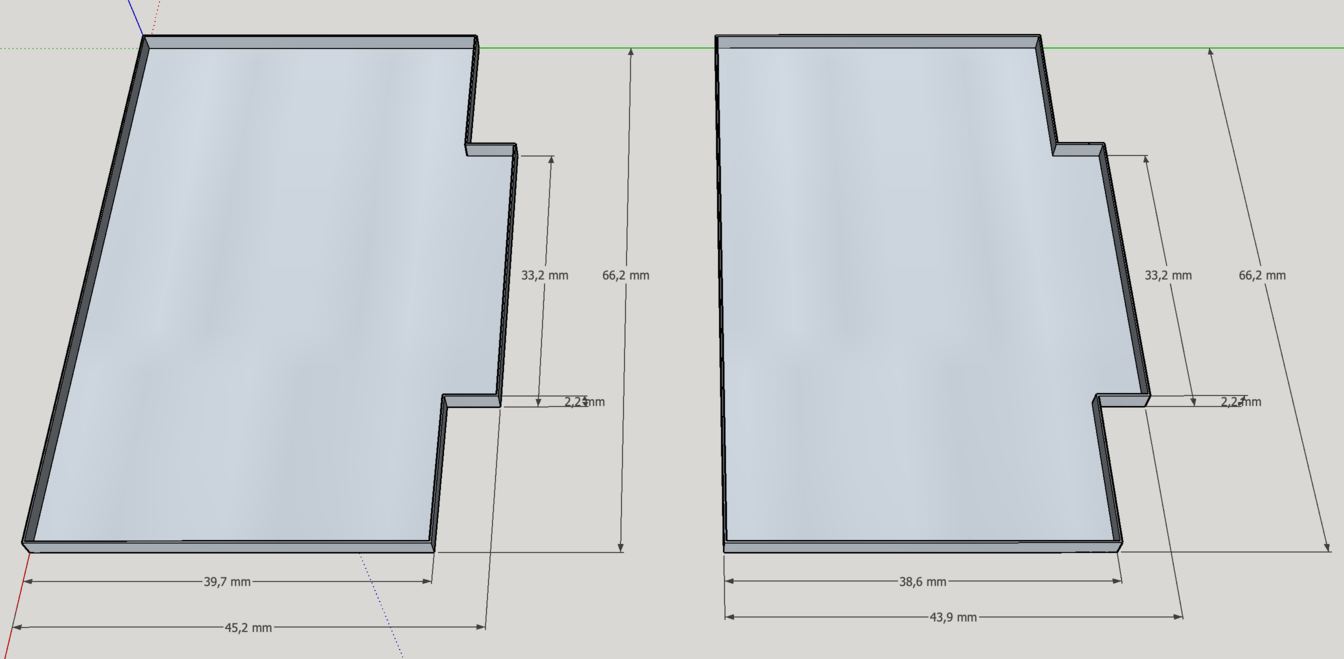
The shields can be soldered directly to the pads on the PCB. Better yet to use shield can clips. Ones that fit the pad layout exactly are S0961-46R from Harwin (see datasheet). Each side will take 8 of those.
As for the material, copper would be the easiest to work with and easy to buy in 0.2 mm sheets from an arts and crafts store. I’d like a factory-made solution, but even though individual cans are cheap to manufacture, ordering them to custom spec would incur an upfront cost of hundreds to thousands of dollars for tooling.
Edit. Shield height for the back side needs further cheks to make sure it won’t touch any components on the main board.
2 Likes
I measured 1.8 mm height of the largest component on the front side of the pcb - have not measured the back.
2 Likes
I had less luck with my method, I tried a very simplistic form: I only covered the front side, as seen in picture:
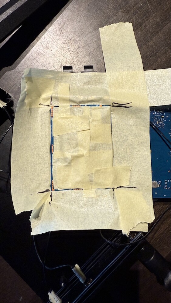
I then placed some aluminium foil on top:
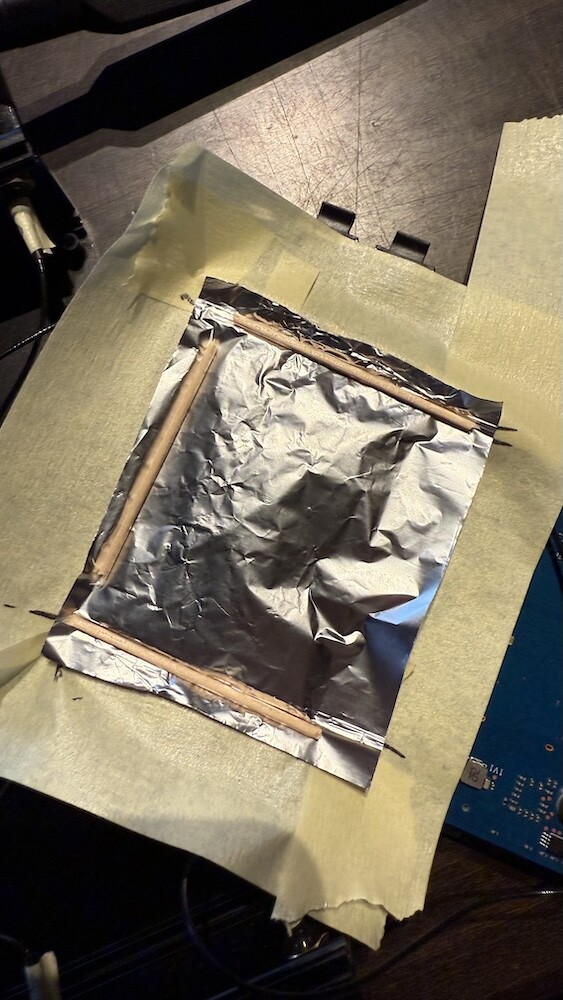
and then applied some pressure, so it will connect the grounding points on the pcb:
But my noise level approximately stayed the same: it was -84 dBm without foil and stayed at -83 dBm with foil. So as you wrote: even a tiny little gap or the missing shielding on the backside and it will not work - I try to add some shielding on the back and report back…
I also ordered some thinner copper foil (0.1 mm and 0.2 mm) together with some kapton tape (for inside isolation with cutout for the 3 chips and will apply some thermal pads between chips and copper) and will solder it on the board when it arrives.
→ EDIT: I now just saw your clips - that would be even better, so I don’t need to solder the copper on the board directly!
I also asked in the OpenWrt One thread for noise levels, as the heatsink also has quite some gap between board and sink.
2 Likes
I also didn’t get any sizable improvement in noise dB until I wrapped the whole module in foil. Connection to ground was probably the issue in your case too. As for the cooling, although I didn’t put any heatsinks or thermal pads under the foil, the Phy ICs were barely touching 70 °C after 5 minutes and there’s no need to run them like this any longer than that.
1 Like
Interesting results, although I’m wondering if copper is better or aluminium as a RF shield
copper should be very good: RF Shielding Material Guide - it is just more expensive than others, so it is probably only used in higher level gear.
2 Likes
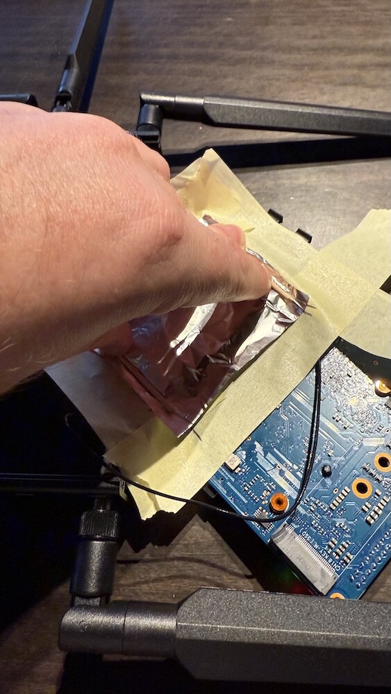
Ok, I also tried shielding the backside and made sure everything is grounded (I placed the aluminium foil next to the screws so when I screwed-in the wifi-board the whole foil got grounded. I measured 0 Ω ground-to-foil).
But at the end I have not seen any improvement, I’m still at approx -84 dBm. But as I just taped down the foil, I still have some air-gap (or tape gap ![]() ) - you seemed to punch holes for the antenna cables?
) - you seemed to punch holes for the antenna cables?
Perhaps -84 dBm is the max we could achieve with this board? - or I’m just lucky to get -84 dBm also with no shielding at all.
But I will nevertheless try a more proper copper shielding - even if it does not help, it might not do more harm.
1 Like
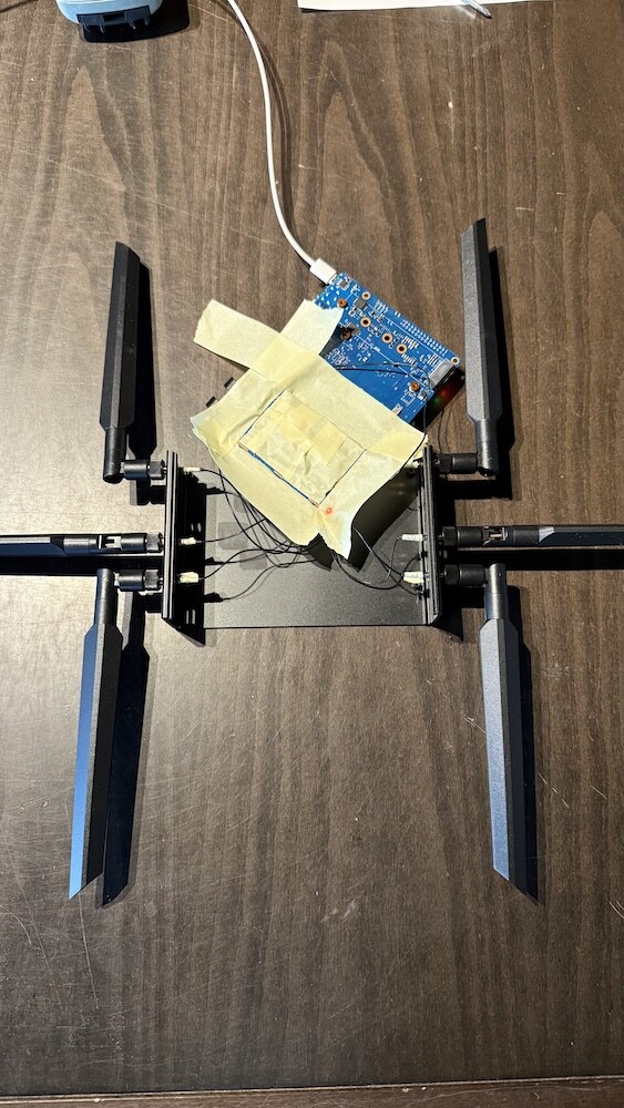
I just fed the pigtails between the top and bottom sheets and compressed the foil around them. What I’d try next is make the sheets larger so that they extend beyond the board area and can be sandwiched together around it. Theoretically, It could be that you’ve hit the limit of what ghetto shielding can do to improve noise if the environment isn’t particularly noisy to begin with (which it seems to be) and now only a properly fitted ‘real’ RF shield will make a difference.
1 Like
At first, I brushed off the idea of bad pigtails. The same 1.13 mm coax cable is used everywhere. Still, it might be worth it to remove the pigtails temporarily (both with and without shielding). Although, I can’t remember if OpenWrt displays any radio stats with no clients connected…
1 Like
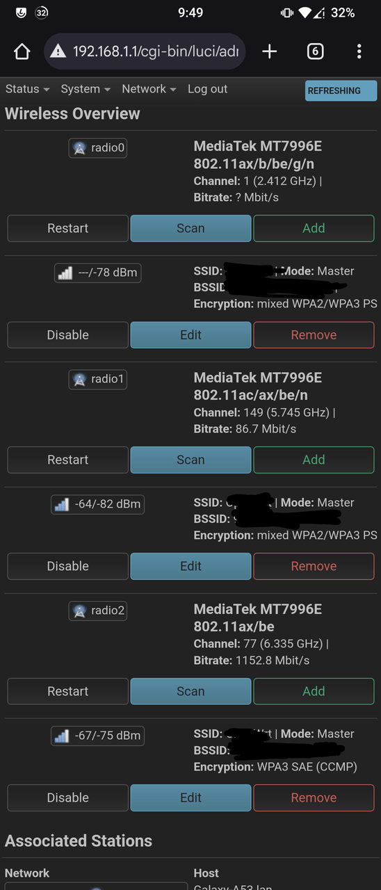
Mine does for the router side not the client side
Just so everyone knows it’s the Taoglas antennas and the RG178 cables, also my ISP router (which is emitting a WiFi signal) is sitting next to my router and 1 TV and 1 monitor and a raspberry pi so yeah I got some serious interference
1 Like
I’m using the same antenna’s + pigtails, range is decent but noise is pretty bad in my case. I think we really need a proper rf-shielding solution from @sinovoip
2 Likes
Yup agreed, one that we shouldn’t pay for due to the fault being on BPI end
1 Like
I did some further testing, now with better control of confounding variables. At baseline the router was out of the housing, no RF shielding, pigtails grounded on the SMA end. Noise level at -80 dB.
Front side RF shielding on the Wi-Fi board made no difference on its own. Back side shielding, however, dropped the noise level to -85 dB. Notably, it didn’t matter whether the foil was grounded or not. Finally, I left a smaller piece of insulated 0.2 mm copper sheet between the Wi-Fi module and the main board and buttoned it up in the housing. Now the noise is staying at -80 to -81 dB, which is the best I ever got from a fully assembled BPI-R4. Although, still far from perfect.
BTW, the type of pigtails (1.13 mm or RG178) didn’t impact noise, at least on the 5 GHz band.
I’m not an electronics engineer, so I might be talking out of my a** now. But to me it looks like the main source of noise is internal to the router since the worst case scenario I found was the stock metal housing. If no extra shielding is added, it could be reflecting the interfering signal right onto the Wi-Fi board. Taking the thing out is already an improvement. Apparently, the BPI-R4 is too small for its own good with that stacked PCB layout.
As for the proper RF shielding, there’s the problem of clearance between the Wi-Fi module and the main board. A solid shield can won’t fit there at all because of the height of SMD components on both sides of the gap. Small cutouts will be necessary to accommodate those. I’ll make a model/drawing of what it should look like.
SinoVoip should at the very least start putting RF shielding on both sides of the BE14 in future batches. Better yet, also make a DIY shielding kit available for a couple of dollars. I doubt they’ll do either, though. I only hope the upcoming BE19 doesn’t end up like this.
1 Like
I guess the bpi-r4 is somehow special, no other bpi product has this layered setup, where the wifi module is on a separate board, so this might be their first such product.
As mentioned, not a single bpi board has any shielding, while you still see left-over shielding traces (would-be shields ![]() ) on those boards - so I guess they got away with no shielding so far, and on bpi-r4 it seems to fail.
) on those boards - so I guess they got away with no shielding so far, and on bpi-r4 it seems to fail.
I have not received a response from OpenWrt One users, but I did a search for “noise” on the forum and found some people posting wifi-stats (with noise level) - and those looked not bad (and again: no shielding on those devices either!):
- BPI-R3-Mini: Noise: -91 dBm
- BPI-R64: Noise: -92 dBm
- BPI-R3: Noise: -99 dBm to -96 dBm (not 100% sure, if they talk about client side noise)
Only a sample size of 2… but nevertheless, they seem to work pretty good with no shielding.
1 Like