Hello! I’ve just got BPI-R4 in my hands, burned image on SD, both switches down, UART adapter connected, everything set aaaand… nothing.
First I was thinking that maybe my adapter is broken, so I decided to bridge tx and rx and was hoping for echo, but no, characters just going as I typing, when I press enter it goes back to the start of the line and overwrite what I type (but tx and rx diodes blinking)
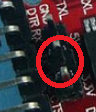
When I connecting it to BPI-R4 there is just blank terminal, I can’t type anything and not reciving any informations, and the diodes are like this:
Even if I pull out sd card and switch to nand or emmc the response is the same (only one difference on nand and emmc is the led is red only, no blinking)
Then I tried atmega 2560 pro clone with 18 and 19 pin but ended with echo (not sure if its good or bad sign)
Yes, I crossed rx and tx
I tried putty and MobaXterm both with: bps 115200, data 8 stop 1, parity none, flow control none
I’m sure I’m using right device, but plot twist, device just died, I mean it’s not even recognized by windows device manager, so there is a chance my code for atmega was faulty and I’ll try to fix it
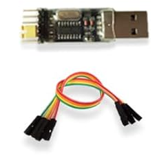
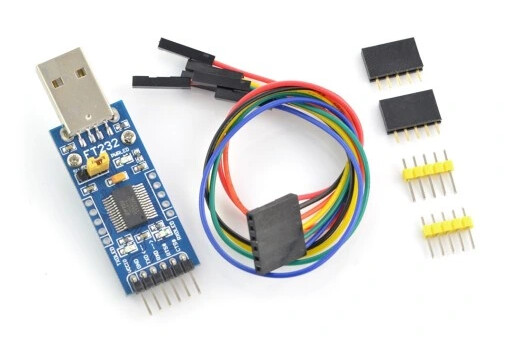
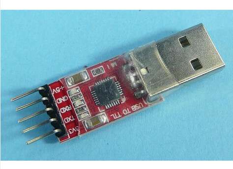
In meantime I’ll order new adapter, but there are only two available in my area:
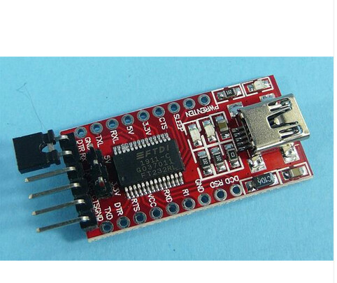
I have some that look like this one. But the jumper is in the wrong place, it should be on the 5V or the 3.3V pin and on the middle pin. Normally they are delivered on the 5V pin and need to be changed over to 3.3V
Just got the device, I moved the jumper to 3.3v, connected tx to rx and rx to tx, gnd to gnd and the same
My last hope is the drivers are bad, what does is say in device manager when you connect the adapter?
Yeah yeah I know, I really appreciate that
I double checked, upluged the adapter, pluged it again and I picked that one was missing before. I think something is wrong with UART on bpi or with bpi itself. I think it’s not bricked since it trying to read from SD, maybe preloader or uboot?
No matter the image, there should always be something to see on the debug uart. Even if the very first part of the image is not ok, you still get errorcodes from the bootrom on the uart.
You are connected to the debug uart? Not to the uart on the gpio header?
No no, I’m connecting to the side debug uart with standalone gnd, tx, rx, not to gpio.
I talked to the seller and he said that board might be damaged, he will send me a new one for now I don’t want to close this topic, let’s wait until I’ll get the new one and see