For R4 power consumption testing, a 12V/2A power supply is sufficient; for R4 + BE14, a PD30W power supply can handle modest loads; however, if all accessories (R4 + BE14 + 10G Ethernet port + 5G + SSD) are included, a power supply of 45W or higher is recommended.
Oh, that is more than I expected. Those wifi chips really need a lot of energy.
I’m currently using a 20V, 1.2A power supply, so 24W max, and use the wifi nic, GPON SFP module and maybe an nvme SSD. Maybe I need to remove the SSD or upgrade my power supply again. Just ordered it two weeks ago, because I thought 24W would be more than enough. I guess I was mistaken.
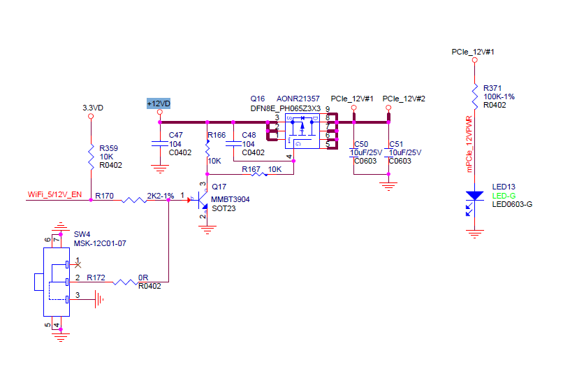
What voltage should the mPCIe power supply for the BE14 be? Is 20V, as specified by the PD power supply, okay? The PCB specifies 12V, but when I turn on SW4, it shows 20V. Will I damage the WiFi card? I can’t find the answer to this question anywhere.
Then, the power supply for the mPICe is switched on via SW4, but it doesn’t turn on the converter, only the MOSFET, and the 20V goes directly to PCIe_12V#1 and PCIe_12V#2. So I’m right in saying that the WiFi card is receiving almost the full voltage from the power supply. Of course, you have to subtract the voltage drops on the diode and MOSFET, but the total is less than 0.5V. So my question is, is this supposed to be the case? Does the BE14 card accept this voltage? I have a damaged WiFi module and I don’t know the cause, and the seller hasn’t contacted me since we both figured out it was faulty" SinoVoip Co.,Limited Banana Pi Store".
I already have a new module and I don’t want it to get damaged when I install it.
CN6 is 20V. Looks like the LED is still working, it’s need arounr 500ohm resistor to bright full light on 12V, 100k resistor provides a lot of reserve, so it’s safe on 20V.
I see there are six MP8759 converters on the BE14 board, so 20V isn’t much for them either. They’re designed for 26V. In principle, everything should work fine. The question is, why is my BE14 damaged? It seems that’s how it was sold to me.
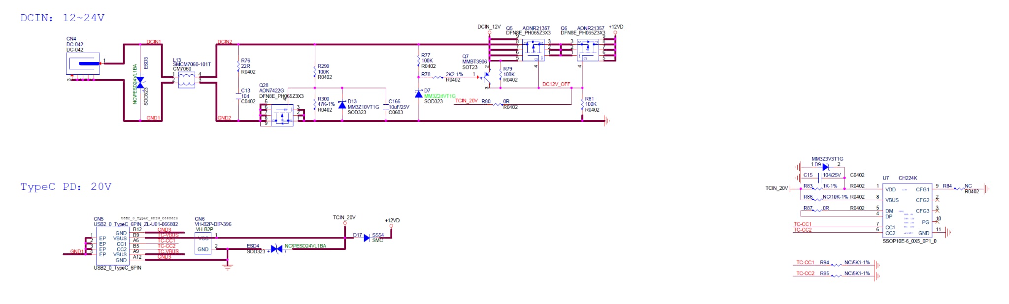
i also wonder about the ch224k section…there is TCIN_20V, but seems no output, TC-CC1/2 seems to be the pins from usb-c socket (configuration pins for selecting usb-voltage?), based on other schematics with this chip output should be pin8 (VBUS) and should be 5V which is connected over an 10K resistor or not connected (not clear in Schematic) to TC20V
You should measure the voltage at pin 9/8/7/6/5 (all same) of Q6. I bet you get 12VDC there (with your 20V USBC-PD). If so, the circuitry is working properly. Your damaged BE14 must be of other reasons, perhaps dead on arrival.
Everything points to a voltage similar to PD on these pins. Unless D7 and D13 somehow control the +12VDC voltage, but it doesn’t seem that way. I don’t recall such a step-down converter, but I don’t know everything. It’s usually based on a buck converter with up and down MOSFETs. From what I understand, this circuit acts as a power source selector at the input. If a PD20V voltage appears, it disconnects the 12-24VDC. I’ll be at the workshop tomorrow and will verify this with a multimeter.
I solved the problem. It turned out that my BPi-R4 board was missing an RU42 49ohm resistor. I figured this out because my old AR24 card only worked in one slot, CN14, it didn’t work in slot CN12. A microscopic inspection revealed that it must have gone somewhere. I replaced the missing component, and everything worked fine.