I want to communicate with this pcie device over spi. What is it needed for the BPI-R3 to recognize this board? is it just a matter of enabling SPI support in the kernel?I’m running 6.3-r3-main
I’m also unsure if I need to modify the dts, this is all new to me so any guidance is welcomed.
You will want to compare the signals you are expecting to use against what the BPI-R3 provides.
I think you’ll find that USB is what you will use, not SPI.
If you plug it in, it should show up if you issue lsusb at the command line.
Unfortunately after that point, how to actually communicate to it is less certain. I’m not sure if it will just enumerate as a CDC type of serial port device, or if it would need a proper USB device driver.
Thanks, the module provides uart, spi, usb lines on the pcie connector so I’m pretty sure it will not work at all on the pcie of the BPI-R3 which is USB only
You should be able to. Although I’m unsure why you’d want to.
If there’s USB support directly on the mini-PCIe interface, this seems like it would be the most straight forward to use (even if a driver is required).
If you go via SPI, then you’ll need to make sure those pins are configured appropriately for SPI (or at least GPIO if you’d go software SPI), and you’d still need to have some kind of driver for it to be supported (regardless of whether that driver is kernel or user-mode).
USB is an enumerated bus, SPI is not. So if you just hook up the SPI you wouldn’t “see the device attached” at all. You’d need to have the chip select sorted out, get it asserted at the right time, send it the right register accesses and data values etc etc before it will work as you’d want. None of this will be out of the box linux (or OpenWRT).
If it is a CDC device, then it would be very close to out of the box linux to at least get communication with it. You’d just need to make sure you’ve got the USB CDC (and USB support) in your kernel. Then at least it would show up.
Getting it doing what you want is the next problem…
I did try the usb route but lsusb doesn’t show it nor does dmesg. Looking at the documentation
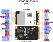
USB Interface - The USB interface mainly provides for the USB_D+, USB_D- pins of the system connector. The USB interface gives access to the configuration register of SX1303 via an MCU STM32L412KBU6. Only the slave side is implemented.
This is the pinout
36
USB_D-
USB_DM
IO
USB differential data (-)
Require differential impedance of 90 Ω
38
USB_D+
USB_DP
IO
USB differential data (+)
Require differential impedance of 90 Ω
So only two pins of the module are used for USB in this pcie form factor.
This is why I’m thinking the only option I have is to go SPI route by connecting(jump cables) bare minimum SPI connections. I see your point about chip select… no idea how to do that although I know this pcie is connected to RPI devices via HAT, so I can look into how RPI does it
The actual USB protocol (v1.x/v2) only has two signals D+ and D-.
The other two signals (GND / +5V) are really just for power (well the GND also tends to be used for a reference for the differential pair… but it’s not really part of the signalling).
There might be a jumper or something required to enable the USB mode.
You’re likely going to run into a trap with the PERST# signal. On the BPI-R3 this is high. According to the RAK webpage, having this high will drive reset of the SX1302. Which would cause you problems.
Not the best design for this to be active high reset in the RAK board connected to an active low reset pin (where it’s expected it would be pulled high).
I’m also unsure if the MCU_NRESET on the RAK board needs an external pull up to release from reset. If it’s pulled down on the RAK board, this would explain why no USB occurs. The MCU is held in reset (since this pin is a N.C. on the BPI-R3).
I suspect the RPI HAT brings out the SPI pins. The BPI-R3 will not. They will terminate at the mini PCIe connector. Since they are reserved signals not intended for connection currently.
Thanks. Interestingly, PERST# on the BPI-R3 seems to be floating… at least according to my multimeter.
The RAK requests PERST# to be pulled down to start USB, so I soldered a 10k resistor between pin 18 GND and 22 PERST# however that didn’t help. Maybe I need to do it via GPIO? I don’t think so.
I’m able to use the RAK via SPI on a raspberry, so I don’t believe it’s damaged.
I purchased the PCIE to USB adapter they sell, let’s see if that makes it work.
I’m still intrigued why the BPI-R3 can’t see it and I don’t have any 4G pcie modem to confirm the port is working.