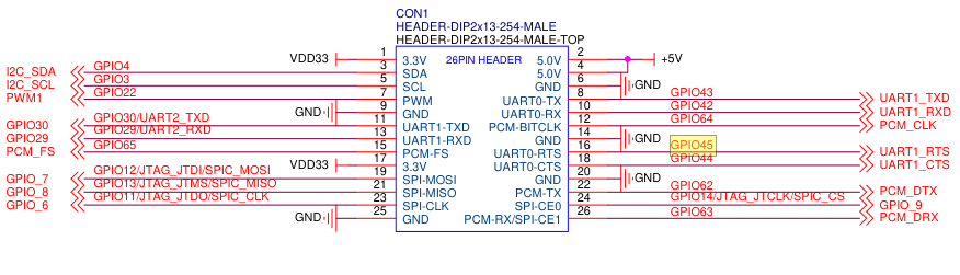
I am making an expansion board for the BPI-R3 and I’m seeing some strange behavior when using CS1 ( as a GPIO CS ) ( I’m Using OpenWRT snapshot ) using
- 21 (MOSI)
- 23 (MISO)
- 25 ( CLK)
- 24 ( SPI_CE0 / GPIO14/SPIC_CS ) as CS0
- 26 ( SPI_CE1/GPIO63 / PCM/DRX ) as CS1
I have created a devicetree overlay to provide 2x spidev devices ( so i can test communication before setting it up for the real devices - MCP2518FD CANBUS ) &spi1 already sets the pin mux and group in the bananapi-r3 devicetree which is set by pinmux:spic_pins
First: using it as SPI1 ( aka “SPIC” ) with mixed CS pins ( native + GPIO )
fragment@3 {
        target = <&spi1>;
        __overlay__ {
		cs-gpios = <0>,<&pio 63 GPIO_ACTIVE_LOW>; // use native CS for CS0, use GPIO CS for CS 1
		num-chipselects = <2>;
		status = "okay";
            spidev1: spidev@0 {
                    compatible = "micron,spi-authenta"; // "spidev" has been deprecated, needs to be assigned a "real" device.
                    reg = <0>;
                    spi-max-frequency = <1000000>;
                    status = "okay";
                };

            spidev2: spidev@1 {
                    compatible = "micron,spi-authenta";
                    reg = <1>;
                    spi-max-frequency = <1000000>;
                    status = "okay";
                };
        };
    };
both spidev devices are created (/dev/spidev1.0 and /dev/spidev1.1 )
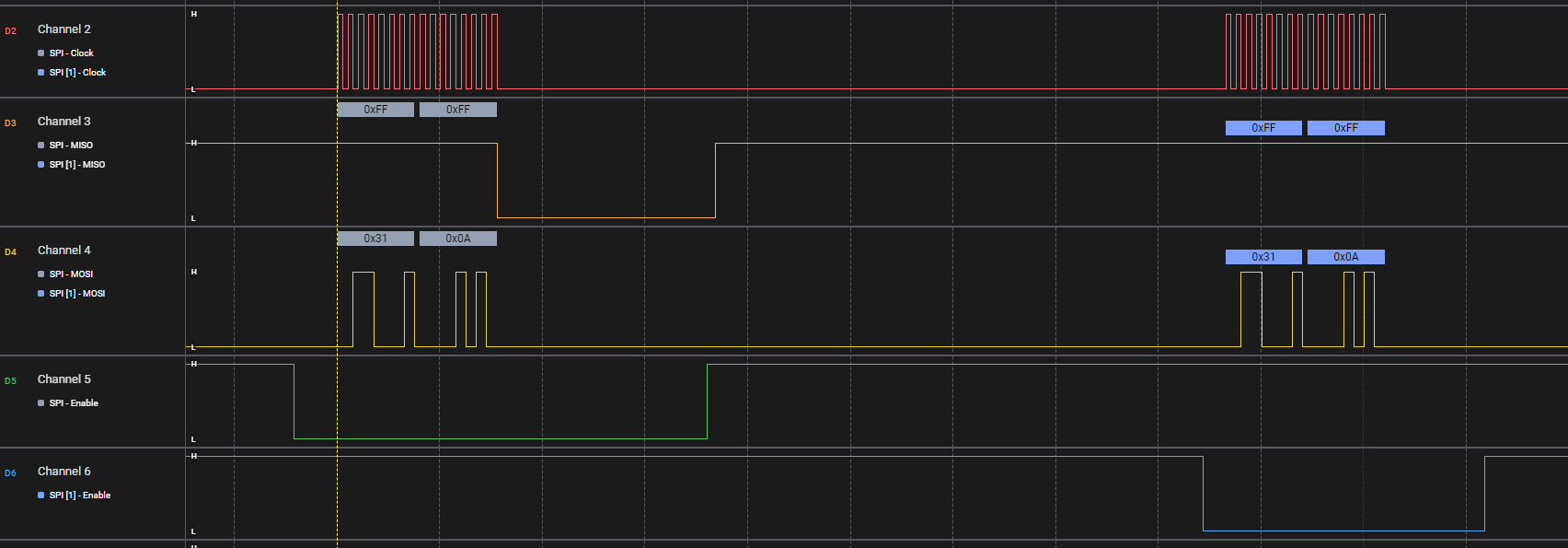
- When I send data to spidev1.0 ( echo ‘a’ > /dev/spidev1.0 ) i see what is expected ( a 1MHZ clock and data on MOSI, CS0 asserted correctly.
- When I send data to spidev1.1 ( echo ‘a’ > /dev/spidev1.1 ) i see a 1MHZ clock and data on MOSI, CS1 asserted correctly, AND CS0 being asserted
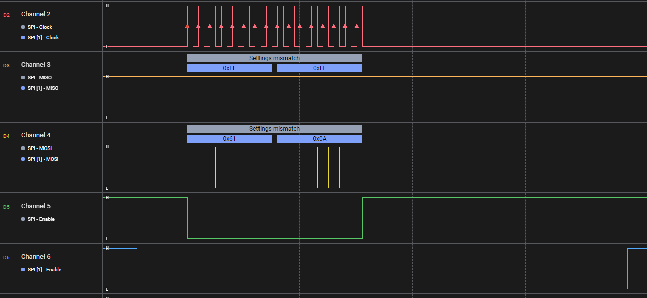
When I change the dts to use both chipselects as GPIO CS ( instead of peripheral controlled/native )
cs-gpios = <&pio 14 GPIO_ACTIVE_LOW>,<&pio 63 GPIO_ACTIVE_LOW>; // use GPIO CS for CS0 and CS1
- spidev1.1 is created ( expected )
- spidev1.0 is not created: get a kernel error message which says "GPIO_9 has already been claimed and pimnux cannot assign it to the port ( also expected, as it seems permanently part of the “spi1_0” group when the “spi” function is used
I see there is a way to set the pads where the GPIO come out using “mediatek,pad-select” in the DTS
mediatek,pad-select:
    $ref: /schemas/types.yaml#/definitions/uint32-array
    minItems: 1
    maxItems: 4
    items:
      enum: [0, 1, 2, 3]
    description:
      specify which pins group(ck/mi/mo/cs) spi controller used.
      This is an array.
- are these the same outputs as when using "spi1_1, spi1_2 and spi1_3 for the group ? ( it seems that way form this Devicetree binding doc )
I also used SPI-GPIO by disabling &spi1 ( so the spic_pins mux is never set ) using MISO,MOSI,CLK , CS0 and CS1 as GPIO
spi_gpio: spi-gpio {
                compatible = "spi-gpio";
                #address-cells = <1>;
                #size-cells = <0>;
                sck-gpios = <&pio 11 GPIO_ACTIVE_HIGH>;
                mosi-gpios = <&pio 12 GPIO_ACTIVE_HIGH>;
                miso-gpios = <&pio 13 GPIO_ACTIVE_HIGH>;
                cs-gpios = <&pio 14 GPIO_ACTIVE_LOW>,<&pio 63 GPIO_ACTIVE_LOW>;
                num-chipselects = <2>;
                status = "okay";
            spidev1: spidev@0 {
                    compatible = "micron,spi-authenta"; // "spidev" has been deprecated, needs to be assigned a "real" device.
                    reg = <0>;
                    spi-max-frequency = <1000000>;
                    status = "okay";
                };
            spidev2: spidev@1 {
                    compatible = "micron,spi-authenta";
                    reg = <1>;
                    spi-max-frequency = <1000000>;
                    status = "okay";
                };
};
- It worked but only at around 100kHz ( expected for bit banged GPIO SPI ), so not practical for using a CANBUS (good enough for port expanders like MCP23S08 )
is there a way for me to use “GPIO_9” / “GPIO14”/SPIC_CS as a GPIO CS by somehow enabling hardware SPI and muxing CS to “nowhere” and using that pin a sa GPIO chipselect as it seems to always assert when the spi1 peripheral is used ? ( possibly by setting the spic_pins in pinctrl for spi1_0 to be 3,3,3,0 so MISO,MOSI,SCK are SPI, but CS is kept as “GPIO” )
a somewhat sanitized MT796A datasheet which helpfully shows the pinmux “aux funtions” which seem to correspond with pinctrl