Adding my 5 cents here, task was to get RTC running. Only for those who are able to do fine soldering on the PCB.
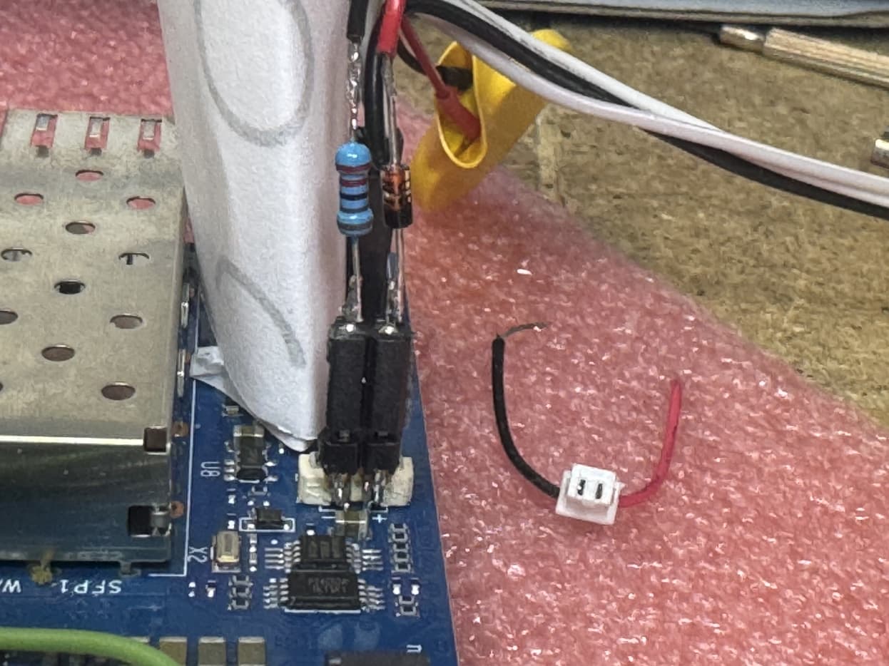
From a previous project I had some coin batteries with fixed cables and at the end the little white plug as shown above. I cut one of the cables from one battery and plugged it into RTC connector on PCB of BPi-R4. Surprisingly there was no voltage at the end of the leads. Likely the width of the contacts in my white plug is wider than the size of the pins in the RTC connector.
So I added a 2.5 mil 2pin header at the back of the RTC connector. and the appropriate plug on other side.
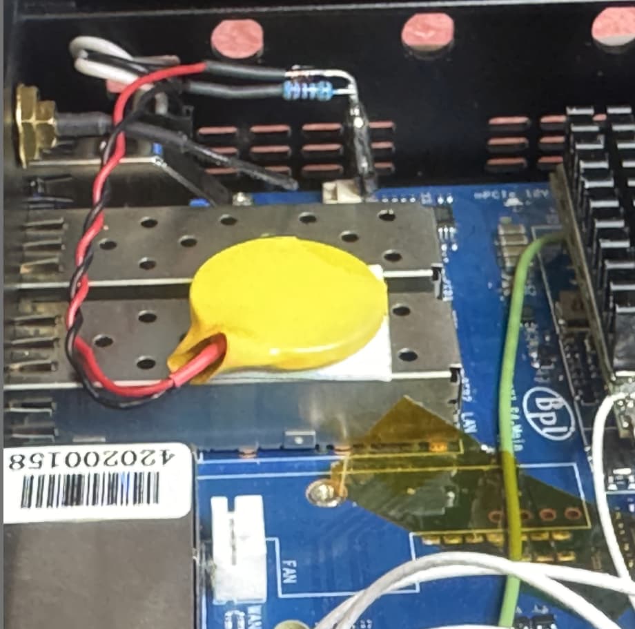
As dicussed above, safety issues to maintain CE, I used a diode 1N4148 and a 2k2 1% resistor, rebuilding the circuitry from the 3.3VD in schematic to supply the RTC from power supply. As the pin header is a pretty good post, I added the elements on the post and soldered the leads of the battery at the other end.
Result: power to RTC can come either from 3.3VD or from coin battery. Tests showed that RTC is now correctly surviving power off even for longer time.
As the RTC header is at the supply voltage of RTC chip, I could use it to do some measurement. It turns out that when applying a power supply, the voltage at the post is little higher than when running on battery. This is good as we do not want unneeded discharge of the battery. The diode prohibits voltage going back or even charging battery. The resistor somewhat limits maximum current at battery, so prohibiting heat by fast discharge. Both elements together add to safety.
At the post, so at RTC supply, I measured some 3.1 V which is pretty enough to run the RTC.
On initial setup, just with pin header, I measured voltage in original state, the capacitor 47 uF runs out pretty fast, it holds for some minute or two to go below 1 V, which is minimum for the RTC chip according data sheet. So the RTC survives on capacitor a quick power reset, but 30 mins or even less will result in voltage loss VL bit set.
For entertainment, some photographs (of the first prototype) follow to show the basic principle:
I have a question regarding replacing the battery for the real-time clock (RTC) in devices. I’m considering using a supercapacitor instead of the standard ML1220 coin cell. Is this a viable option, and what potential issues could arise?
I know that supercapacitors (ionistor) can maintain voltage for extended periods, but they have different characteristics compared to lithium coin cells. Could this affect the proper functioning of the RTC or other components?
I would appreciate any advice or experience regarding the use of supercapacitors in such applications!