Hi,
Its not clear to me from the BPI documents. Does the BPI-R3 or BPI-R4 have a Real time clock? I.e. something that keeps time between being powered off and on
Hi,
Its not clear to me from the BPI documents. Does the BPI-R3 or BPI-R4 have a Real time clock? I.e. something that keeps time between being powered off and on
R3 does not have one,r4 has one,but not yet tested due to missing cable for battery connector
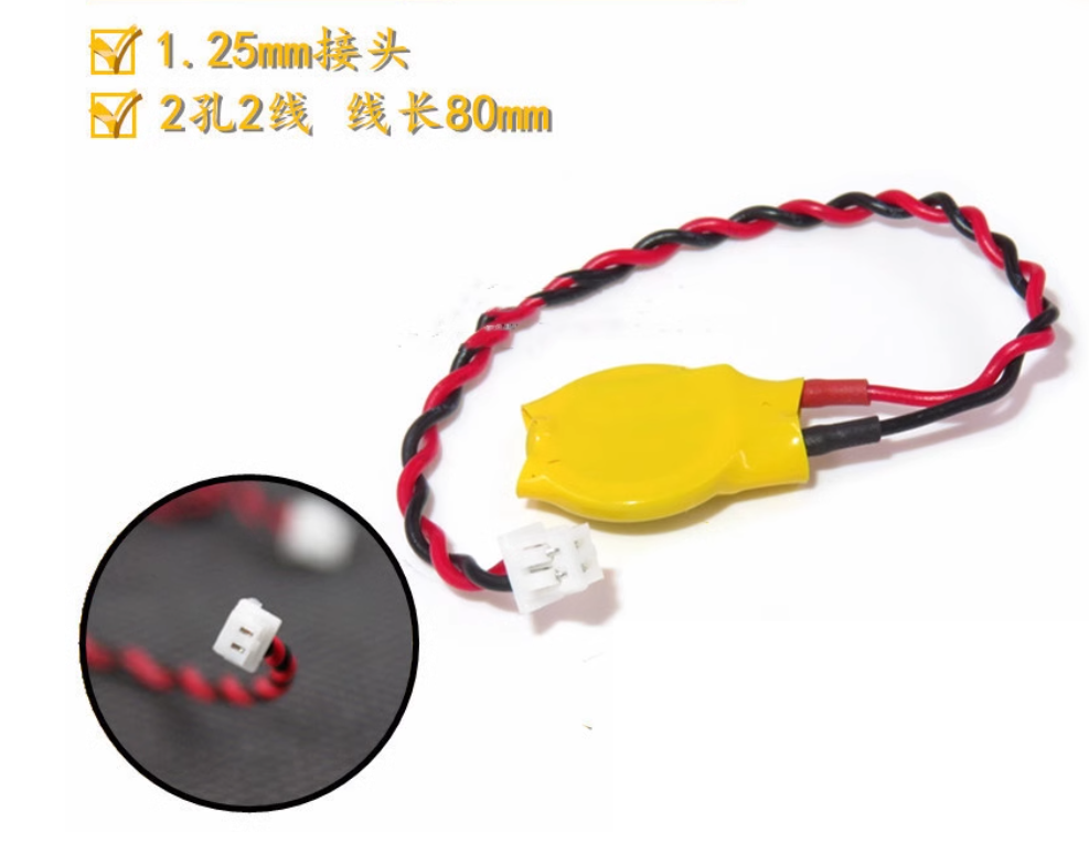
@sinovoip @simon can you tell us which kind of cable is needed for the rtc connector
Do not see such cable on aliexpress,but can build own using the jst cable and a battery socket.
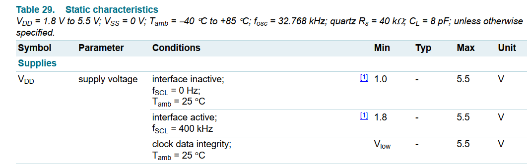
Which voltage is the battery? Vcc_rtc is 3v3,which is uncommon voltage for batteries, cn batteries are mostly 3v7, cr20xx similar to your picture are 3v
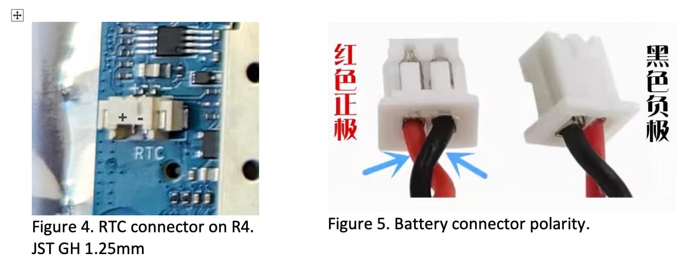
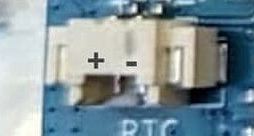
Ok,found some while searching “cmos cr2032”,but all have long shipment of >2months. I try to build my own, so i can set also polarity…is this right on the picture above?
Yes, because it’s a battery it can’t be shipped by air, that’s why it takes so long.
The picture is correct, please also pay attention to the label beside the slot.
Thx, i ordered
https://de.aliexpress.com/item/32808433102.html https://de.aliexpress.com/item/1005001859554796.html And https://de.aliexpress.com/item/1005005606126356.html
Just for others as reference, there is a 8 day shipping instead of 2 months.
Lets see which battery holder is better for powering the rtc.
in the time while shipping i tried to get rtc itself running but currently fail due to trace
[    1.930574] ------------[ cut here ]------------
[    1.935187] WARNING: CPU: 0 PID: 1 at drivers/irqchip/irq-gic-v3.c:1706 gic_i
rq_domain_select+0x15c/0x204
[    1.944750] Modules linked in:
[    1.947798] CPU: 0 PID: 1 Comm: swapper/0 Not tainted 6.9.0-rc1-bpi-r4 #2
[    1.954575] Hardware name: Banana Pi BPI-R4 (DT)
[    1.959181] pstate: 00400005 (nzcv daif +PAN -UAO -TCO -DIT -SSBS BTYPE=--)
[    1.966131] pc : gic_irq_domain_select+0x15c/0x204
[    1.970913] lr : gic_irq_domain_select+0xac/0x204
[    1.975606] sp : ffffffc08190b4b0
[    1.978909] x29: ffffffc08190b4b0 x28: 0000000000061a80 x27: ffffff80bf9d9258
[    1.986036] x26: 0000000000000001 x25: ffffff80bf9d9240 x24: ffffffc0816414d8
[    1.993163] x23: ffffffc080e58728 x22: ffffffc080e58728 x21: 0000000000000000
[    2.000288] x20: ffffff80000cd000 x19: ffffffc08190b5c8 x18: ffffffffffffffff
[    2.007413] x17: 0000000000000001 x16: ffffffc080e482a8 x15: ffffff800001a77a
[    2.014539] x14: ffffffffffffffff x13: ffffff800001a778 x12: 0000000000000001
[    2.021664] x11: 752f3a6e69622f3a x10: 000000000006f948 x9 : 0000000000000005
[    2.028789] x8 : ffffffc08190b6e8 x7 : 0000000000000000 x6 : 070f1900f2f2f5f0
[    2.035914] x5 : ffffffc080e58728 x4 : 00000000a110c8ee x3 : ffffffc08190b4ec
[    2.043040] x2 : ffffffc08190b4f0 x1 : ffffffc08190b5c8 x0 : 00000000ffffffea
[    2.050166] Call trace:
[    2.052602]  gic_irq_domain_select+0x15c/0x204
[    2.057035]  irq_find_matching_fwspec+0xf4/0x124
[    2.061644]  irq_create_fwspec_mapping+0x3c/0x354
[    2.066338]  irq_create_of_mapping+0x68/0x90
[    2.070598]  of_irq_get+0x98/0xd8
[    2.073906]  i2c_device_probe+0x24c/0x2e4
[    2.077908]  really_probe+0xc0/0x38c
[    2.081474]  __driver_probe_device+0x7c/0x15c
[    2.085820]  driver_probe_device+0x40/0x110
[    2.089992]  __device_attach_driver+0xbc/0x158
[    2.094425]  bus_for_each_drv+0x80/0xdc
[    2.098251]  __device_attach+0xa8/0x1d4
[    2.102077]  device_initial_probe+0x14/0x20
[    2.106250]  bus_probe_device+0xac/0xb0
[    2.110076]  device_add+0x5a0/0x78c
[    2.113557]  device_register+0x20/0x30
[    2.117297]  i2c_new_client_device+0x16c/0x358
[    2.121731]  of_i2c_register_device+0xbc/0xe4
[    2.126079]  of_i2c_register_devices+0x84/0x15c
[    2.130600]  i2c_register_adapter+0x1f0/0x700
[    2.134946]  i2c_add_adapter+0x78/0xd0
[    2.138685]  mtk_i2c_probe+0x4e8/0x648
[    2.142425]  platform_probe+0x68/0xdc
[    2.146078]  really_probe+0xc0/0x38c
[    2.149644]  __driver_probe_device+0x7c/0x15c
[    2.153990]  driver_probe_device+0x40/0x110
[    2.158163]  __driver_attach+0xf4/0x1fc
[    2.161988]  bus_for_each_dev+0x74/0xd0
[    2.165814]  driver_attach+0x24/0x30
[    2.169379]  bus_add_driver+0x110/0x214
[    2.173205]  driver_register+0x60/0x128
[    2.177031]  __platform_driver_register+0x28/0x34
[    2.181725]  mtk_i2c_driver_init+0x1c/0x28
[    2.185815]  do_one_initcall+0x44/0x260
[    2.189643]  kernel_init_freeable+0x200/0x3cc
[    2.193992]  kernel_init+0x20/0x1d4
[    2.197470]  ret_from_fork+0x10/0x20
[    2.201036] ---[ end trace 0000000000000000 ]---
a=03
[    2.213388] rtc-pcf8563 1-0050: pcf8563_probe: write error
i2cdetect seems to see the rtc at 0x50 (only eeprom @ 0x57 is not seen, but maybe 0x51), 0x70 is the i2c mux
root@bpi-r4-v10:~# i2cdetect -y 1
     0  1  2  3  4  5  6  7  8  9  a  b  c  d  e  f
00:                         -- -- -- -- -- -- -- --
10: -- -- -- -- -- -- -- -- -- -- -- -- -- -- -- --
20: -- -- -- -- -- -- -- -- -- -- -- -- -- -- -- --
30: -- -- 32 -- -- -- -- -- -- -- -- -- -- -- -- --
40: -- -- -- -- -- -- -- -- -- -- -- -- -- -- -- --
50: 50 51 -- -- -- -- -- -- -- -- -- -- -- -- -- --
60: -- -- -- -- -- -- -- -- -- -- -- -- -- -- -- --
70: UU -- -- -- -- -- -- --
any idea what this could be?
my dts looks like this:
+++ b/arch/arm64/boot/dts/mediatek/mt7988a-bananapi-bpi-r4.dts
@@ -235,6 +235,22 @@ &i2c2 {
        pinctrl-0 = <&i2c2_1_pins>;
        status = "okay";

+       pcf8563: rtc@50 {
+               compatible = "nxp,pcf8563";
+               reg = <0x50>;
+               interrupts = <&pio 6 IRQ_TYPE_LEVEL_LOW>;
+               #clock-cells = <0>;
+               //status = "disabled";
+       };
+
+       eeprom@57 {
+               compatible = "atmel,24c02";
+               reg = <0x57>;
+               address-bits = <8>;
+               page-size = <8>;
+               size = <256>;
+       };
+
        pca9545: i2c-switch@70 {
Something with irq domain fails…but why
trace seems to be related to the interupts property, so i disabled it, but rtc still gives this (on r4v1.0 board):
 # dmesg | grep -i rtc
[    1.930765] rtc-pcf8563 1-0050: pcf8563_write_block_data: err=-6 addr=0e, data=03
[    1.938247] rtc-pcf8563 1-0050: pcf8563_probe: write error
[    1.943751] rtc-pcf8563 1-0050: probe with driver rtc-pcf8563 failed with error -5
also tried 0x51 as i see this address in other threads while searching
and i wonder why the adresses 0x50 and 0.51 disappeared from i2cdetect after i added the rtc driver…
changed address to 0x51 seems to fix it…at least it is recognized
root@bpi-r4-v11:~# dmesg | grep rtc
[    1.480017] rtc-pcf8563 2-0051: low voltage detected, date/time is not reliable.
[    1.487496] rtc-pcf8563 2-0051: registered as rtc0
[    1.493498] rtc-pcf8563 2-0051: low voltage detected, date/time is not reliable.
[    1.500888] rtc-pcf8563 2-0051: hctosys: unable to read the hardware clock
Hi
Have you just fixed this? i.e. rtc on a different device number? I.e. correct bus number, a typo with the device number.
Yes with adress 0x51 it seems to work,but have to wait for battery cable
Hi,
I tested the RTC patch. It works. BPI-R4 now returns date/time with “hwclock” and /dev/rtc0 is present.
Isn’t it just a common ‘cmos battery’ found on the internet?
This one: 4 euro (incl shipping or 2 euro if you buy some other product also), 5 pcs, 7 day delivery.
I guess yes,but this one is not shippable to germany…all similar had this long shipment so i just ordered holder+cable
Weird, to Holland no problem…
This one can ship to germany ![]()
I bought an RTC battery from Amazon (because I wasn’t feeling patient, haha) and thought I’d post a picture of it installed. I haven’t patched OpenWRT yet but I can confirm that it fits with the correct polarity. Was a bit of a bother to get it inserted into the socket but it eventually clicked.
For reference, you can use any RTC battery that’s compatible with DELL D830 ![]()
At least you get one ‘Made in Japan’ Not sure it’s cell only or the whole assembly.
I was researching RTC battery for R4 over the weekend. Perhaps I should share my notes if anyone in the same boat as me:
Red (with pins seen facing on top) +ve. Black -ve.
There are also other possibilities:
In this case you do not have to use the JST connector.
But it needs the use of a soldering iron ![]() .
.
how do you connect to r4 here?
Thanks for the question!!!
I thought the connector on the R4 PCB is a THD component but its a SMD ![]()
![]()
But it is possible to unsolder it!
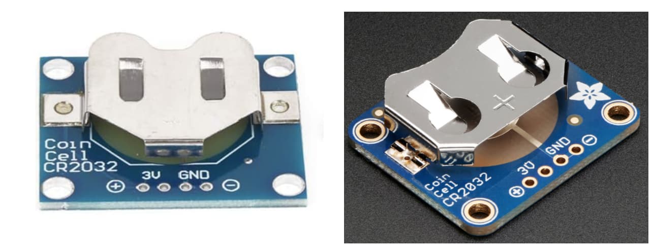
May be its better to use a usual PH 2 connector (hope it is right) and just solder it in the little PCB with CR 2032 connector:
The Idea is to mount this in the case and just use the battery …
And the good part is → “we” can buy it on amazon germany ![]()
So in the R4 the schematic:
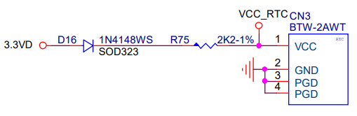
So isn’t this a charging circuit?
So would we need a LiR-2032 or ML-2032, instead of a CR-2032 ?
Edit:
With VD at 5V this would make sense as a charging circuit, but here VD is 3.3V. Or is the voltage drop over the diode enough to make sure the battery does not get charged?