Just use without diode for testing, I do not think you will immedeately burn your house down. You would be present anyway. But just to be on the safe side, remove the battery after testing, as it is not following the battery manufacturer specifications.
@riskable also seems to have survived the experience. Appropriate nickname here
In my previous tests i get an error from rtc when it is probed…but yes,maybe i only need to save the clock first and then do only software reboots for testing if the clock survives this…but after poweroff the clock will be reset of course. I always poweroff the boards when not working on them. But problem is on poweron that battery may get hot because it is charged…adding the diode may prevent this and battery damage
Hi, thanks for sharing your wisdom, can you help me with this question, can these RTC batteries for Raspberry Pi 5 be placed on the BPI-R4? The 2-pin JST connector is a bit longer, but I think the pitch connector is still 1.25mm.
You can use the ML2032 in any device which accepts CR2032, but you CAN’T use the CR2032 in devices which accept the ML2032, because the CR2032, being non-rechargeable, might EXPLODE when trying to be recharged.
The 47uF capacitor at VCC_RTC is the hero (thanks to BPI for putting it there). From my back of the envelope calculation, enough electricity to power the RTC for 4-5 hours if not longer when main DC power is off.
To R4 owners:
for all intents and purposes, you don’t need a RTC battery like I said before.
[    1.486064] rtc-pcf8563 2-0051: setting system clock to 2024-04-27T11:22:02 UTC (1714216922)
[    1.486000] rtc-pcf8563 2-0051: setting system clock to 2024-04-27T18:42:44 UTC (1714243364)
I helped an OpenWrt user to enable the RTC in snapshot for BPI R4. And enabled the RTC for myself as a byproduct. So took the chance to test how long the RTC can survive offline without a battery.
My BPI R4 is 4 hours. RTC keeps the time perfectly fine.
Maybe you have more client-devices which taking current…maybe there is a current backflow over serial-uart…i saw the power led is dimmed when uart is connected…possibly i had not cut off all connections (also using a switchable dc-connector).
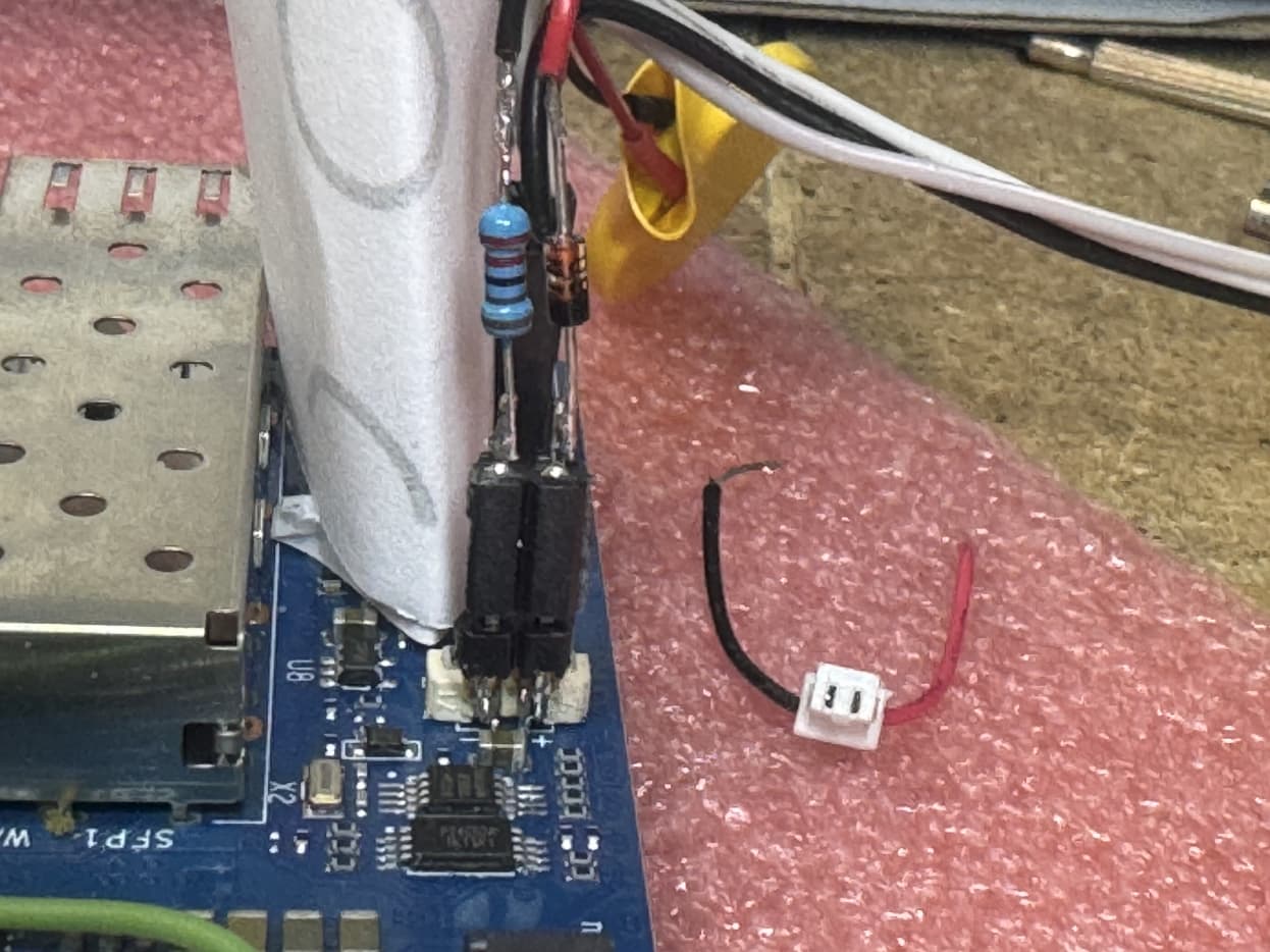
Adding my 5 cents here, task was to get RTC running. Only for those who are able to do fine soldering on the PCB.
From a previous project I had some coin batteries with fixed cables and at the end the little white plug as shown above. I cut one of the cables from one battery and plugged it into RTC connector on PCB of BPi-R4. Surprisingly there was no voltage at the end of the leads. Likely the width of the contacts in my white plug is wider than the size of the pins in the RTC connector.
So I added a 2.5 mil 2pin header at the back of the RTC connector. and the appropriate plug on other side.
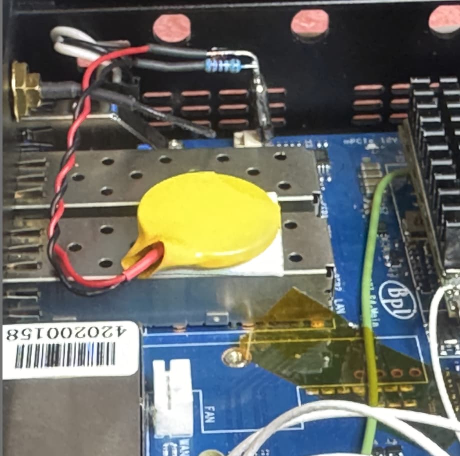
As dicussed above, safety issues to maintain CE, I used a diode 1N4148 and a 2k2 1% resistor, rebuilding the circuitry from the 3.3VD in schematic to supply the RTC from power supply. As the pin header is a pretty good post, I added the elements on the post and soldered the leads of the battery at the other end.
Result: power to RTC can come either from 3.3VD or from coin battery. Tests showed that RTC is now correctly surviving power off even for longer time.
As the RTC header is at the supply voltage of RTC chip, I could use it to do some measurement. It turns out that when applying a power supply, the voltage at the post is little higher than when running on battery. This is good as we do not want unneeded discharge of the battery. The diode prohibits voltage going back or even charging battery. The resistor somewhat limits maximum current at battery, so prohibiting heat by fast discharge. Both elements together add to safety.
At the post, so at RTC supply, I measured some 3.1 V which is pretty enough to run the RTC.
On initial setup, just with pin header, I measured voltage in original state, the capacitor 47 uF runs out pretty fast, it holds for some minute or two to go below 1 V, which is minimum for the RTC chip according data sheet. So the RTC survives on capacitor a quick power reset, but 30 mins or even less will result in voltage loss VL bit set.
For entertainment, some photographs (of the first prototype) follow to show the basic principle:
I have a question regarding replacing the battery for the real-time clock (RTC) in devices. I’m considering using a supercapacitor instead of the standard ML1220 coin cell. Is this a viable option, and what potential issues could arise?
I know that supercapacitors (ionistor) can maintain voltage for extended periods, but they have different characteristics compared to lithium coin cells. Could this affect the proper functioning of the RTC or other components?
I would appreciate any advice or experience regarding the use of supercapacitors in such applications!