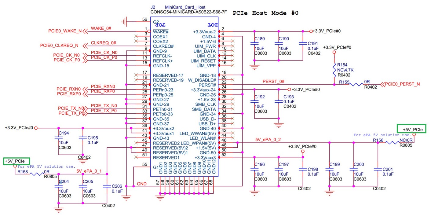
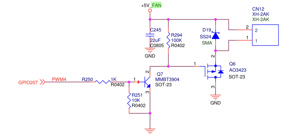
Just measured it. If I’ll measure voltage between the pins, I do get nothing. But if I’ll take Positive pin (the closest to IR) and take some other ground, like screw plate or metal shielding of USB ports, I do get stable 2.66V
After running bellow:
echo 4 > /sys/class/pwm/pwmchip0/export
echo 10000 > /sys/class/pwm/pwmchip0/pwm4/period
echo 5000 > /sys/class/pwm/pwmchip0/pwm4/duty_cycle
echo normal > /sys/class/pwm/pwmchip0/pwm4/polarity
echo 1 > /sys/class/pwm/pwmchip0/pwm4/enable
I do get negative 5V, meaning it looks like the port has reversed polarity (towards the connector/fan combo)
Then, I took a look to pwm subsystem:
root@ap-unimatrix:/etc# cat /sys/kernel/debug/pwm
platform/11006000.pwm, 5 PWM devices
 pwm-0   ((null)              ): period: 0 ns duty: 0 ns polarity: normal
 pwm-1   ((null)              ): period: 0 ns duty: 0 ns polarity: normal
 pwm-2   ((null)              ): period: 0 ns duty: 0 ns polarity: normal
 pwm-3   ((null)              ): period: 0 ns duty: 0 ns polarity: normal
 pwm-4   (sysfs               ): requested enabled period: 10000 ns duty: 5000 ns polarity: normal
root@ap-unimatrix:/etc#
So it looks like the fan was enabled, but the port has reversed polarity,although it calls it normal.
I tried to reverse it, using:
echo inverse > /sys/class/pwm/pwmchip0/pwm4/polarity
But it returned an error of invalid argument. What is the right way to reverse the polarity, so I don’t have to solder the conector?
Anyway, this looks like an error on my side - and on my side only. I’ve ordered two new fans of the same dimensions, and I will play with the solder pen tomorrow, to use better socket/pin header in order to make sure I do have a connection between fan and the socket pins. maybe my fan is faulty to begin with, since I am certain I do get 5V out of the socket now.
Anyway, thanks a lot for tips!