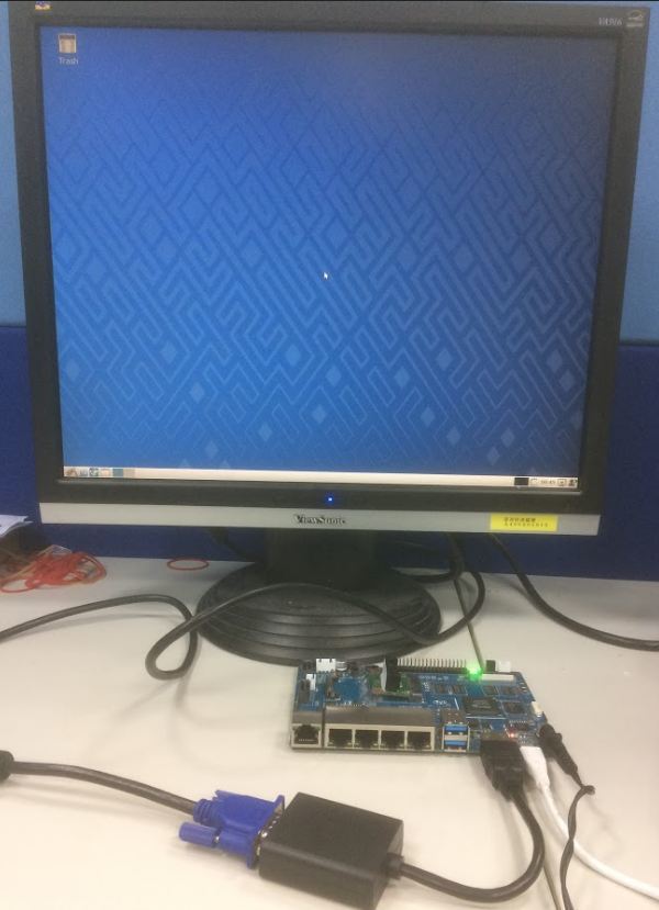
try to remove kvm or use hdmi to connect to tv directly.
I think this is just because “ubuntu”. Debian jessie works fine on my HDMI->VGA converter.
How to do auto power-on and auto start?
Hi, on directly connected to TV is ok I have just problem with HDMi/VGA convertor(With or without KVM)!
I’d like to know how to get it to autoboot as well. It feels sort of useless as a router if it doesn’t autoboot after power failure…
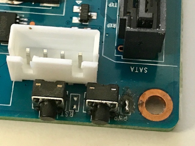
I’ve played a bit with pwr button, and it seems that is button can only power-on, and does nothing when system is off (does’nt power-off, and it seems that no signal is sent to the operating system). My understanding of the schematics of the bpi-r2 leaded to the same conclusion.
So, I soldered the 2 pins just next the power button. And now, my bpi-r2 automatically boots when power cord is plugged. Gotcha !
5 Likes
Can bpi-support confirm this (without resistor)?
I see next to reset are 2pins,too…are these the pins for reset-switch (to bridge these with transistor base-connected to arduino over 1k resistor for remote-reset)?
1 Like
That’s great news. I’m a bit disappointed at the designer to add a power-switch like this to a router design… At least it could have been an normal jumper connector there as well to bypass the power-switch… Great work - hope that they confirm this is how to get it done. I’m not holding my breath though.
We are seeing the same behavior. It boots instantly in this situation. We have seen others who are bridging and bypassing the power button to get the same results. Most people using this board seem to want the device to boot on power connected and the have a reset button since it is basically a router platform.
Questions is why does the unit boot instantly when the OTG in connected to a device providing 5V? I assume that the power switch controls the MT6323, so can Firmware for the MT6323 be set with to boot on 12v to the barrel connector?
can BPI-Team confirm this can be done??
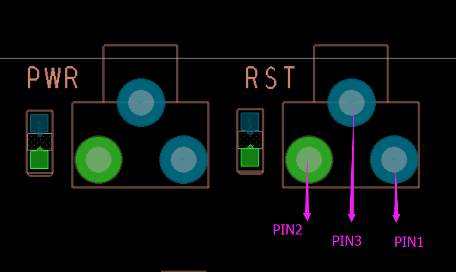
The two PIN beside the Reset is used as system reset, and it is not recommended to weld anything else unless you know the hardware very well
Hi simon,
first i mean the pins beside power-switch (which have been solded together by 2 persons here successfully)
the second one are the pins for reset or the 3 solder-points from the switch itself (i measured 2 go to gnd like in shematics, the other one is bridged to the others if switch pressed)…my idea is to make a simple circuit with transistor (1 of the gnd-points to Emitter, the other to Collector, base over resistor to an arduino-pin) to do a remote-reset
1 Like
Yes,you can do that.
It is recommended to weld on the PIN of the Reset switch
The picture is a top view
2 Likes
thanks for the Picture, how about the solder-bridge of power (for poweron without button-press)
Can you please publish a rework instruction to remove the power switch, that will allow the system to boot on inserting the power cord, and only power off with the power cable is removed? If this could maintain a reset option that would be ideal. Right now having to hold down the power switch and monitor the LED is not a good user experience.
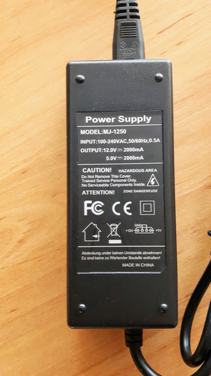
For anybody interested I share my idea on how to power R2 including the attached HDDs. As I need to run R2 with two HDDs (one of 2.5" and second of 3.5" size) I had to sort out the problem of how to power it all optimally. After some googling I found power brick that provides both 12V and 5V outputs via standard molex connector. And that did the trick for me.
As you can see from the picture below I power the 2.5" disk from R2 but the 3.5" one directly from power adaptor via molex as I’m not sure if R2 can provide enough current to spin it up (didn’t try it though). I also brought 5V from adaptor to microUSB port on R2 to make it boot automatically after power lost.
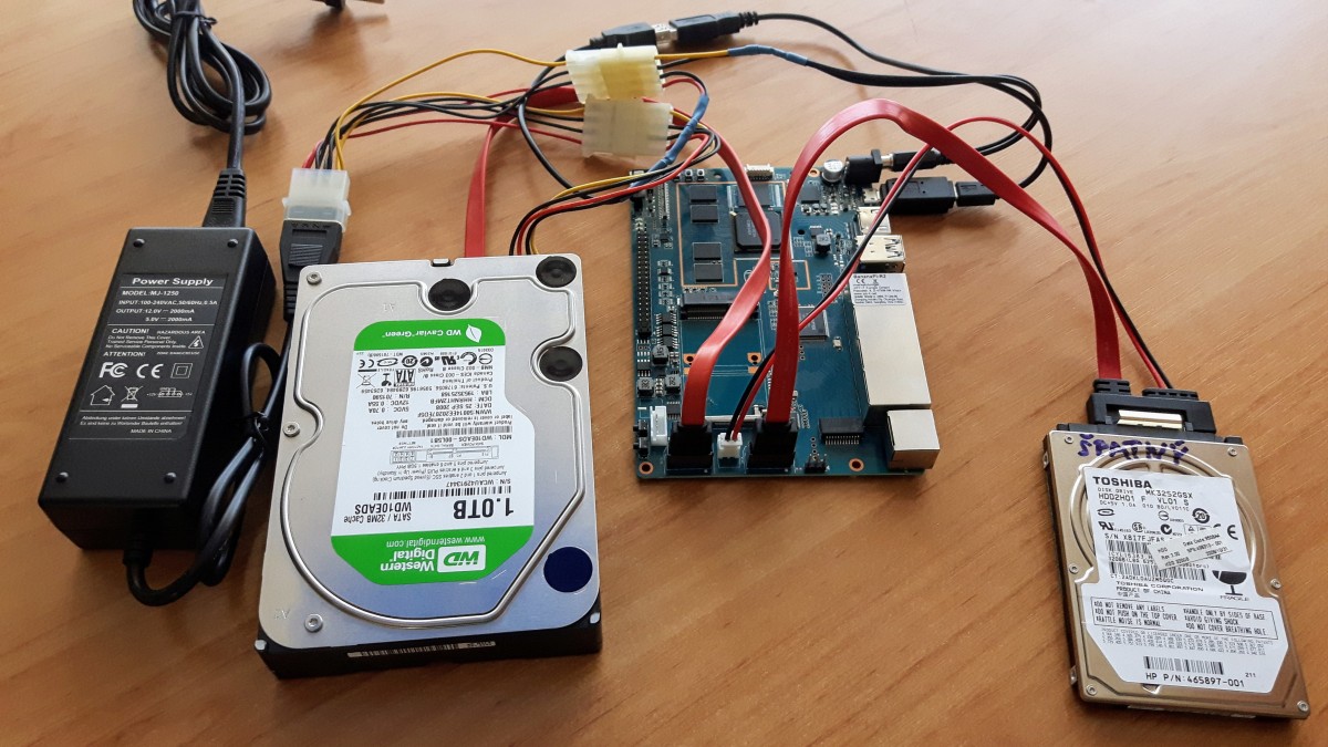
Here is the detail of the power brick. It is rated 2A for both 5V and 12V output lines. Unfortunately not clear if meant simultaneously, ie. 4A in total or not. But it works well in my setup. I have attached a dual DVB-T USB donge to R2 too.
1 Like
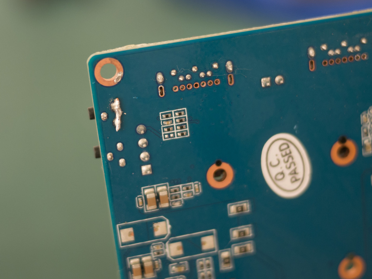
Thanks. It’s a lot easier to bridge PIN1 and PIN2 than solder the tiny pads. Take a piece of wire (I clipped off a pin from some spare header pins) and lay it from PIN1 to PIN2. Then just solder each end down. You may want to tape the wire in place or something while you’re soldering.
Here’s a photo of my horrible soldering:
1 Like
thank you bburky, i’m waiting for official response, that is the right way and nothing will be damaged (if you solder properly of course)
Thank you, that have worked for me.
Hello, I cloudn’t understand what you mean exactly. For what did you use this solution? I need to use 3.5 HDD. Thanks