BPI-Pico-S3 has the same dimension as the Raspberry Pi Pico board, equipped with an ESP32S3 chip, an 8MB flash, 4-layer PCB, electroplated half-hole process, ceramic antenna, supports 2.4 GHz Wi-Fi and Bluetooth® LE dual-mode wireless communication, it’s a development board perfect for IoT development and Maker DIY Projects.
TinyUF2 + CircuitPython is built-in at the factory.
It is recommended to use Mu Editor to get started with CircuitPython development.
YouTube
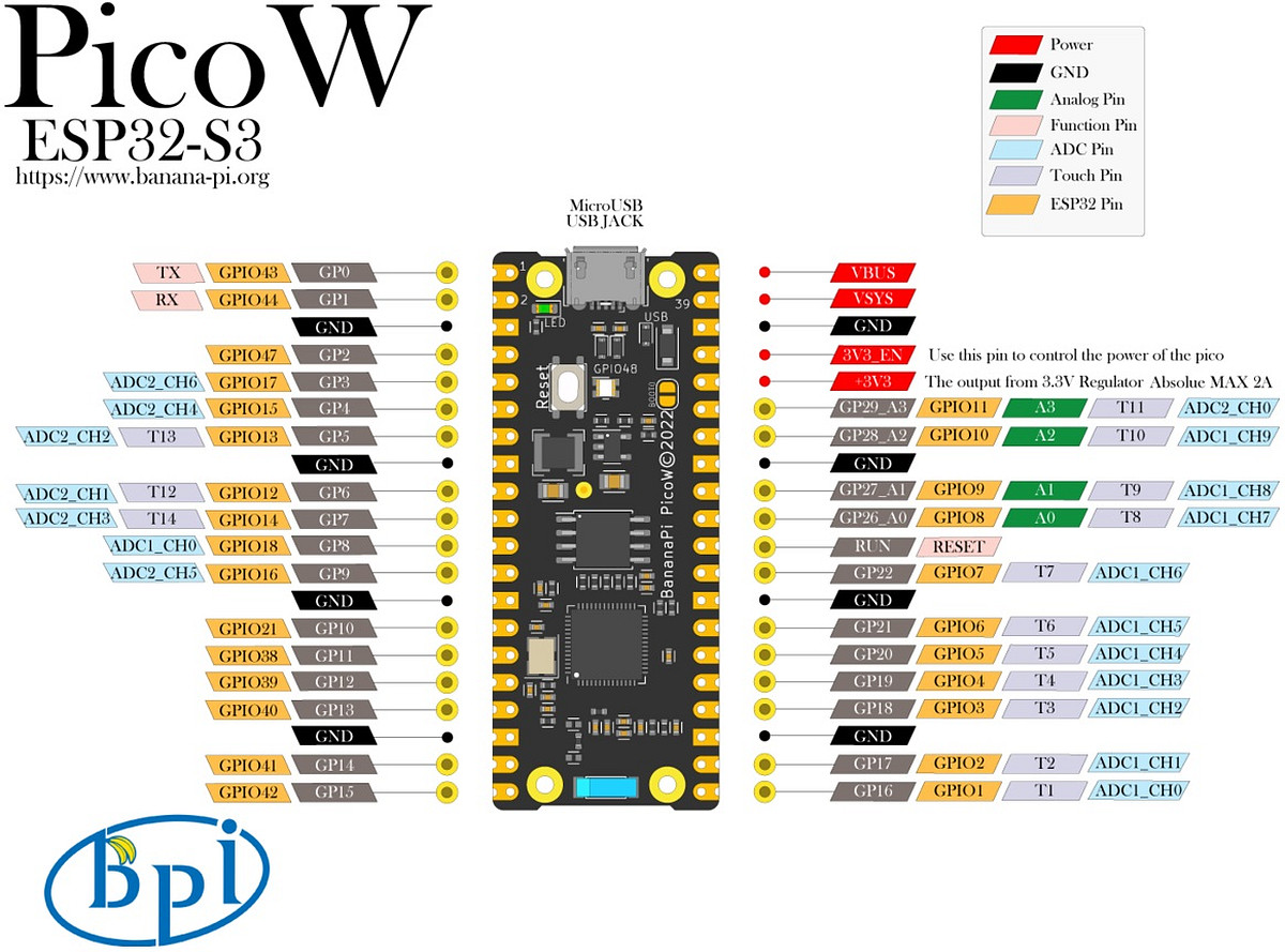
Hardware interface
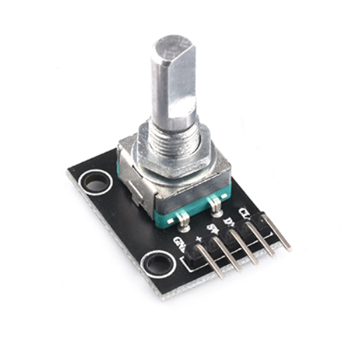
Using incremental rotary encoders
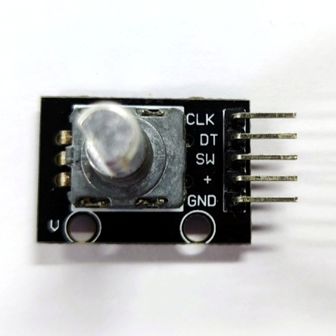
Wiring reference
| Incremental rotary encoder | BPI-PicoW-S3 |
|---|---|
| GND | GND |
| + | VBUS |
| SW | |
| DT | GP0 |
| CLK | GP1 |
-
The appearance of the incremental rotary encoder is similar to some common rotary potentiometers, but there are three key differences.
-
The microcontroller uses the ADC peripheral to read the analog signal (voltage value) output by the rotary potentiometer to determine the current angular position of the shaft. The microcontroller receives the digital signal output by the incremental rotary encoder through GPIO, and can judge the movement of the rotating shaft corresponding to the signal through the software program.
-
Within a certain range of accuracy, the microcontroller can determine the current angular position of the rotary potentiometer shaft, but due to the continuity of the analog signal and poor anti-interference ability, it cannot accurately determine whether it has an action. The incremental rotary encoder sends a digital signal to the microcontroller only when the rotating shaft moves to a contact point, if an incremental rotary encoder has 20 contacts in one revolution, it will trigger 20 action signals for one revolution, and the microcontroller can accurately determine whether it moves, in which direction it turns, and how many times the signal is triggered.
-
Rotary potentiometers usually cannot rotate infinitely in any direction, and will stop at the maximum or minimum limit points. But incremental rotary encoders can rotate infinitely in any direction.
-
-
Incremental rotary encoders use quadrature encoders to generate their A and B output signals. The pulses emitted from the A and B outputs are encoded in quadrature, which means that when the incremental encoder is moving at a constant velocity, the A and B waveforms are square waves with a 90 degree phase difference between A and B. Eventually the A and B signals will be delivered to the microcontroller from two pins.
-
Theoretically, at any given time, for a rotary encoder, there is a phase difference of +90° for clockwise rotation and −90° for counterclockwise rotation between the A and B signals, it depends on the design of the quadrature encoder inside the device.
-
The pulse frequency on the A or B output is proportional to the speed (rate of change of position) of the shaft. A higher frequency means a faster speed, while a lower frequency means a slower speed. When the shaft is stationary, the static, constant signal output is on A and B, so there are many speed measurement schemes using incremental rotary encoders.
- Use CircuitPython to design a program to read the signals on the GP0 and GP1 pins, and when one of them changes, output the values of the two pins at the same time, connect the development board and the incremental rotary encoder and run the program.
import board
import digitalio

dt = digitalio.DigitalInOut(board.GP0)
clk = digitalio.DigitalInOut(board.GP1)
dt.switch_to_input()
clk.switch_to_input()
dt_last_value = 0
clk_last_value = 0

while True:
    if dt.value != dt_last_value or clk.value != clk_last_value:
        dt_last_value = int(dt.value)
        clk_last_value = int(clk.value)
        print((dt_last_value,clk_last_value))
-
Turn the rotating shaft step by step to observe the output signal. If there is a logic analyzer or oscilloscope, it can also be connected to observe.
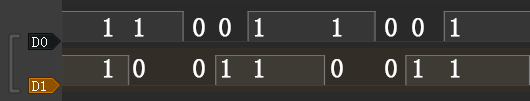
- When the shaft rotates counterclockwise, the REPL output:
(1, 1) (1, 0) (0, 0) (0, 1) (1, 1) (1, 0) (0, 0) (0, 1) (1, 1)-
When the shaft rotates counterclockwise, the waveform observed by the logic analyzer:
-
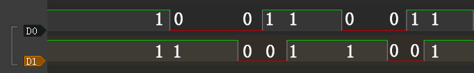
When the shaft rotates clockwise, the REPL output:
(1, 1) (0, 1) (0, 0) (1, 0) (1, 1) (0, 1) (0, 0) (1, 0) (1, 1)- When the shaft rotates clockwise, the waveform observed by the logic analyzer:
-
The first thing that can be observed is that the signals on the two pins are both 1 after the shaft completes the first level of motion. Based on this, the program can be designed to output a count value when both the values of the two pins become 1, and this count value can be used as the basis for judging that the encoder has completed an action.
import board
import digitalio

dt = digitalio.DigitalInOut(board.GP0)
clk = digitalio.DigitalInOut(board.GP1)
dt.switch_to_input()
clk.switch_to_input()
dt_last_value = 0
clk_last_value = 0
count = 0

while True:
    if dt.value != dt_last_value or clk.value != clk_last_value:
        dt_last_value = int(dt.value)
        clk_last_value = int(clk.value)
        print((dt_last_value,clk_last_value))
        if (dt_last_value,clk_last_value) == (1,1):
            print('--',count_1,'--')
            count += 1
-
Then determine the law and difference of the signal output on the two pins when the encoder rotates clockwise and counterclockwise.
-
The law of counterclockwise rotation is (1, 1)>(1, 0)>(0, 0)>(0, 1)>(1, 1) .
-
The law of clockwise rotation is (1, 1)>(0, 1)>(0, 0)>(1, 0)>(1, 1) .
From this, we can design a program that rotates clockwise to make the count +1, and rotates counterclockwise to make the count -1, and add the function of debounce and error correction.
-
import board
import digitalio
import time
dt = digitalio.DigitalInOut(board.GP0)
clk = digitalio.DigitalInOut(board.GP1)
dt.switch_to_input()
clk.switch_to_input()
dt_last_value = 0
clk_last_value = 0
count = 0
start_sign = 0
clockwise_sign = 0
while True:
    if dt.value != dt_last_value or clk.value != clk_last_value:
        dt_last_value = int(dt.value)
        clk_last_value = int(clk.value)
        print((dt_last_value,clk_last_value))
        if start_sign == 0 and (dt_last_value,clk_last_value) == (0,0):
            start_sign = 1
        elif start_sign == 1:
            if (dt_last_value,clk_last_value) == (1, 0):
                clockwise_sign = 1
            elif (dt_last_value,clk_last_value) == (0, 1):
                clockwise_sign = -1
            elif (dt_last_value,clk_last_value) == (1, 1):
                count = count + clockwise_sign
                clockwise_sign = 0
                start_sign = 0
                print('--',count,'--')
-
The implementation of the debounce and error elimination function in this program is not to gradually judge whether the verification conforms to the signal law. There may be more ways to achieve debounce and error elimination. Welcome to discuss.
-
In addition, the
rotaryiomodule of CircuitPython can directly realize the function of counting the forward and reverse. There are some differences in the internal procedures, but the final functions are basically the same.
import rotaryio
import board

encoder = rotaryio.IncrementalEncoder(board.GP0,board.GP1)
last_position = 0

while True:
    position = encoder.position
    if position != last_position:
        print(position)
    last_position = position
BPI-PicoW-S3 + CircuitPython Tutorial Aggregation Link
BUY BPI-PicoW-S3 :
-
OEM&OEM customized service: [email protected]