BPI-Pico-S3 has the same dimension as the Raspberry Pi Pico board, equipped with an ESP32S3 chip, an 8MB flash, 4-layer PCB, electroplated half-hole process, ceramic antenna, supports 2.4 GHz Wi-Fi and Bluetooth® LE dual-mode wireless communication, it’s a development board perfect for IoT development and Maker DIY Projects.
TinyUF2 + CircuitPython is built-in at the factory.
It is recommended to use Mu Editor to get started with CircuitPython development.
YouTube
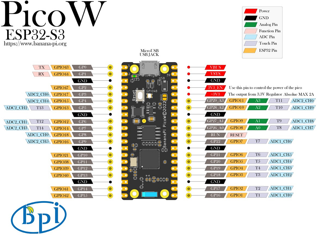
Hardware interface
PWM Controlled Servo
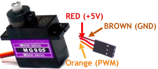
Take the MG90S servo as an example, refer to its corresponding manual for other servo, and modify the corresponding parameters in the following codes.
-
- The key parameters of MG90S servo:
-
Control angle, 0° ~ 180°
-
PWM duty time control, 500us ~ 2500us corresponds to 0° ~ 180°
-
Operating Voltage: 4.8V to 6V (5V typical)
-
Stall torque: 1.8 kg/cm (4.8V)
-
Maximum stall torque: 2.2 kg/cm (6V)
-
Operating speed is 0.1s/60° (4.8V)
-
The expression of the duty time required to find any rotation angle is:
 Let y be the duty time and x be the rotation angle
 y=(2500-500)/180*x+500
 y=(100*x+4500)/9
-
According to the parameters, it can be determined that the angle of the steering gear is controlled by the duration of the high level of the PWM wave. And since the control of the steering gear must be controlled by a periodic PWM waveform, the duration of one cycle must exceed the duty time required to control the steering gear to reach 180°, that is, if it exceeds 2500us, the PWM frequency should be lower than 400hz.
-
Set the PWM frequency to 200hz, then the cycle duration is 5000us, and the corresponding duty cycle for controlling the servo to rotate from 0° to 180° is 10% to 50%.
-
The PWM duty cycle control precision of CircuitPython is 16bit, 100% duty cycle is expressed as 1111 1111 1111 1111 in binary, FFFF in hexadecimal, and 65535 in decimal.
-
The expression for finding the duty cycle required for any rotation angle is:
Let y be the duty cycle and x the rotation angle
y=((50-10)/180*x+10)/100*65535
y=(4369*x+196605)/30
- The wiring method of the servo and BPI-PicoW-S3:
td {white-space:pre-wrap;border:1px solid #dee0e3;}The VBUS pin of BPI-PicoW-S3 can output +5V; except GP0, all GP pins can be used to output PWM, just need to modify the corresponding pin in the program.
| MG90S | BPI-PicoW-S3 |
|---|---|
| GND brown | GND |
| +5V red | VBUS |
| PWM orange | GP0 |
- According to the above expressions and parameters, design a program that can arbitrarily control the rotation angle of this servo:
import board
import pwmio
import time
servo_1 = pwmio.PWMOut(board.GP0, frequency=200, duty_cycle=0)#200hz, one cycle 5000us

def get_duty_cycle(x):
    return int((4369*x+196605)/30)

servo_1.duty_cycle = get_duty_cycle(90)# 90 degrees
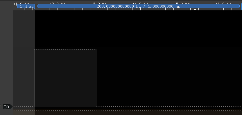
- The PWM duty time of the output controlled by this program can be read out through a logic analyzer, which should be consistent with the calculated value.

- Use a list to design a set of consecutive servo actions:
import board
import pwmio
import time
servo_1 = pwmio.PWMOut(board.GP0, frequency=200, duty_cycle=0)#200hz, one cycle 5000us

def get_duty_cycle(x):
    return int((4369*x+196605)/30)

action_list1 = [0,45,90,135,180,0,180,45,135,90]

while True:
    for i in action_list1:
        servo_1.duty_cycle = get_duty_cycle(i)
        time.sleep(0.5)
BPI-PicoW-S3 + CircuitPython Tutorial Aggregation Link
BUY BPI-PicoW-S3 :
-
OEM&OEM customized service: [email protected]