Hi, can anyone indicate to me the physical location of bridge (0 Ohm resistor) R31 on the PCB of the BPI-M4? I have the DXF files, but cannot see any component labels. R31 is in the nRST line of the eMMC, and I want to add a switch that allows to enable/disable the eMMC so I can choose to boot from µSD even when then eMMC has a bootloader.
Hello friend, your title is M5, but you asked about M4. Which board’s information do you actually need?
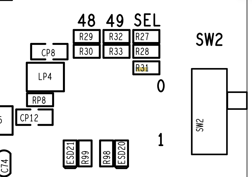
Hi, many thanks for your reply, and sorry for the confusion. My board is an M5. Do you have the information for that board as well?
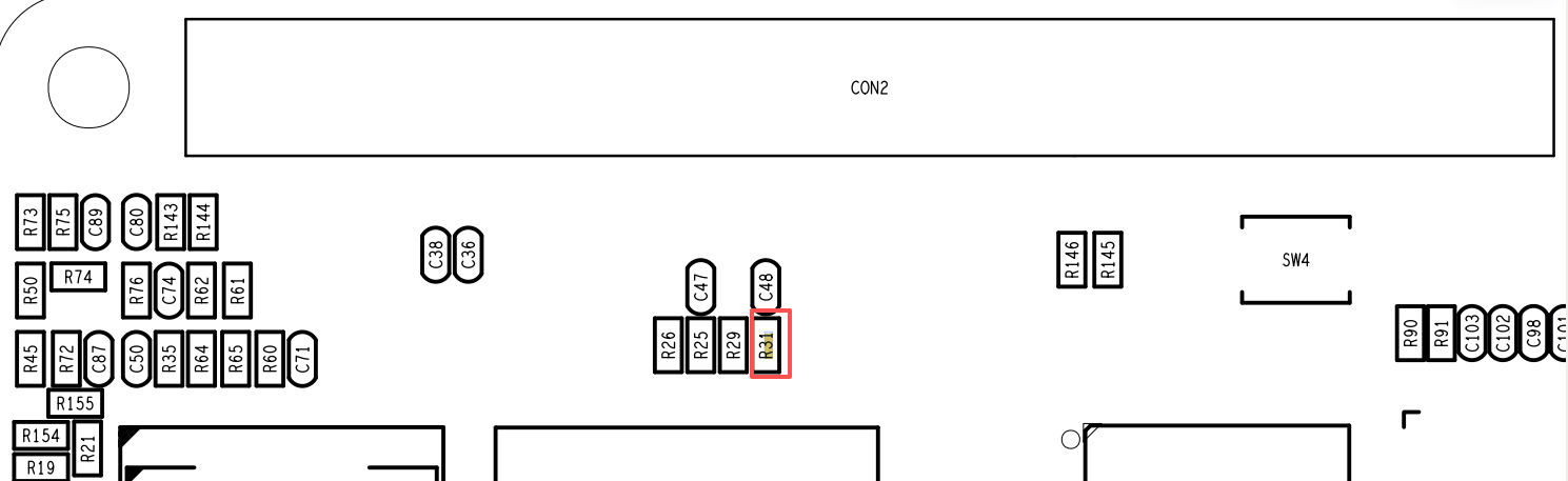
Thanks a lot! This is very useful.
Hi again! Just to let you know how the intended modification went: After removing R31 and pulling eMMC_RST_C to ground via 1 kOhm, the SoC still booted from eMMC (I checked contacts and voltages; I am sure the eMMC reset input is permanently at GND level). This is unexpected, because “mmc extcsd read /dev/mmcblk1” shows “[RST_N_FUNCTION]: 0x01”, meaning the reset pin should be enabled. However, pulling eMMC_CMD to GND via 1 kOhm safely prevents initial communication with the eMMC, making the boot ROM start from µSD. The eMMC_CMD signal is accessible at one pin of R25, which is also visible in the picture you posted. I will add a switch allowing to choose the boot source. Thanks again for your help!
I’m glad I could help you, you’re welcome.