I have problems detecting insertion of an SD card into the slot on BPI-CM4 . Both with our custom designed breakout board and also with the origianl IO board.
All connections on the CM4 board and the IO board are documented in the schematic diagram. I don’t understand the schematic.
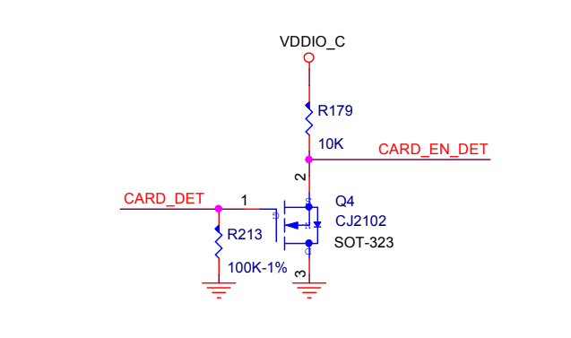
RPI-CM4 board:
IO board:
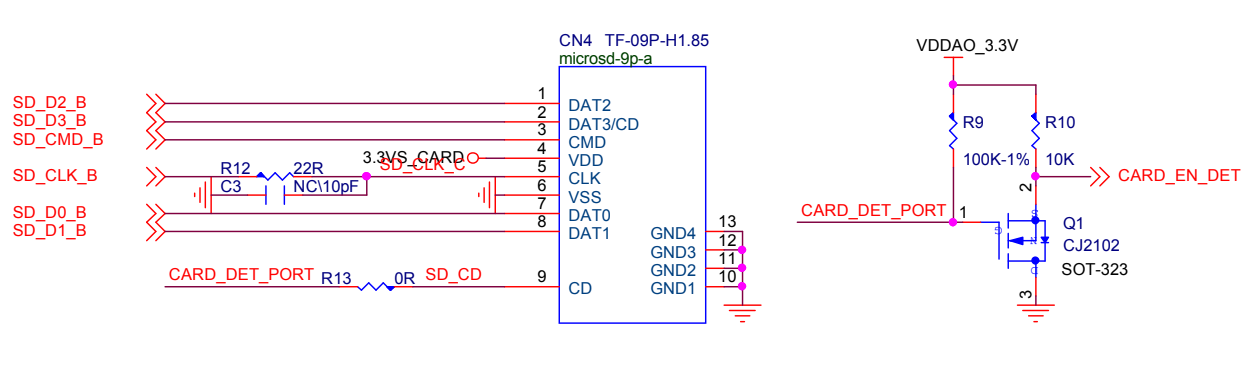
Both N-mosfet transistors (Q1 and Q4) does not seem to be correctly connected. Their D and S pins are switched. Then they would for as level inverters between various voltage rails. But if connected like this the transistor on the IO board only switches between 0 and 0.6V and the second does not work at all. It almost looks like a mistake in the schematic. Is it correct on the actual PCBs?
I realize the card detection is critical for data transfers. But I would like to understand the implementation to be able to design our own breakout boards with correct schematic.
Thanks.