Build Armbian Ubuntu Mantic CLI image
$ git clone https://github.com/BPI-SINOVOIP/armbian-build.git -b v24.04.30 armbian-build
$ cd armbian-build
$ ./compile.sh BOARD=bananapif3 BRANCH=legacy RELEASE=mantic BUILD_DESKTOP=no BUILD_MINIMAL=no KERNEL_CONFIGURE=no INSTALL_HEADERS=yes COMPRESS_OUTPUTIMAGE=sha,xz
More info about Armbian build, Please refer to Armbian.
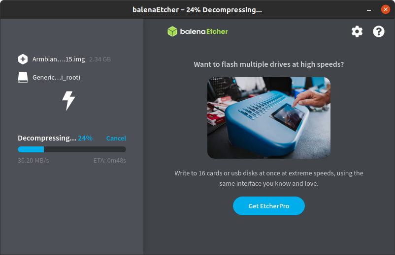
After build finish, Flash armbian-build/output/images/Armbian-bpi-SpacemiT_24.5.0-trunk_Bananapif3_mantic_legacy_6.1.15.img.xz to sdcard with BalenaEtcher.
Insert sdcard to bananapif3 board, power on and finish the Setup Wizard.
Enable 26pin I2C4, SPI3, UART5 and PWM7
The latest Spacemit bsp is not support kernel DTS Overlay, so modify the dtb with dtc command to enable 26pin i2c4, spi3, uart5(pin8 and pin10 R_UART0 not support), pwm7.
If you are familiar with armbian build source code and compilation process, you can add a kernel patch that enables the relevant 26-pin functions to your local code, allowing you to skip this step.
If future versions support DTS overlay, the 26-pin functions can be enabled through a DTS overlay.
root@bananapif3:~# cd /boot/dtb/spacemit
root@bananapif3:~# cp k1-x_deb1.dtb k1-x_deb1.dtb.org
root@bananapif3:~# dtc -I dtb -O dts -o k1-x_deb1.dts k1-x_deb1.dtb
root@bananapif3:~# vi k1-x_deb1.dts

	//i2c4
	i2c@d4012800 {
		status = "okay";
	};

	//spi3
	spi@d401c000 {
		status = "okay";
	};

	//pwm7
	pwm@d401bc00 {
		status = "okay";
	};

	//uart5
	uart@d4017400 {
		status = "okay";
	};

root@bananapif3:~# dtc -I dts -O dtb -o k1-x_deb1.dtb k1-x_deb1.dts
root@bananapif3:~# reboot
Confirm I2C4, SPI3, UART5, PWM7 enabled
root@bananapif3:~# ls /dev/i2c-4
/dev/i2c-4

root@bananapif3:~# ls /dev/spidev3.0
/dev/spidev3.0

root@bananapif3:~# ls /dev/ttyS4
/dev/ttyS4

root@bananapif3:~# ls -l /sys/class/pwm/pwmchip0/
total 0
lrwxrwxrwx 1 root root    0 Sep 10 16:11 device -> ../../../d401bc00.pwm
--w------- 1 root root 4096 Sep 10 16:11 export
-r--r--r-- 1 root root 4096 Sep 10 16:11 npwm
drwxr-xr-x 2 root root    0 Sep 10 16:09 power
lrwxrwxrwx 1 root root    0 Sep 10 16:08 subsystem -> ../../../../../../class/pwm
-rw-r--r-- 1 root root 4096 Sep 10 16:08 uevent
--w------- 1 root root 4096 Sep 10 16:11 unexport
WiringPi
root@bananapif3:~# git clone https://github.com/Dangku/WiringPi
root@bananapif3:~# cd WiringPi
root@bananapif3:~# ./build
gpio command
root@bananapif3:~/WiringPi# gpio -v
gpio version: 3.6
Copyright (c) 2012-2024 Gordon Henderson and contributors
This is free software with ABSOLUTELY NO WARRANTY.
For details type: gpio -warranty

Hardware details:
  Type: k1-x deb1, Revision: 01, Memory: 8192MB
  Maker: Bananapi, Chip-Vendor: Spacemit

System details:
  Kernel version: 6.1.15-legacy-k1
  Device tree present.
  Model: spacemit k1-x deb1 board
  Root or sudo required for direct GPIO access.

root@bananapif3:~/WiringPi# gpio readall
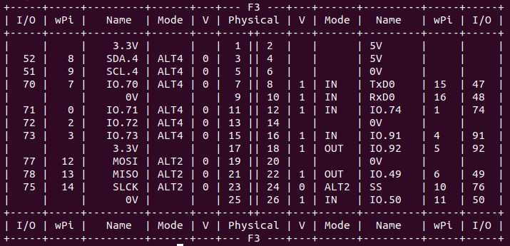
gpio set phy pin.26 high/low
root@bananapif3:~/WiringPi# gpio mode 11 out
root@bananapif3:~/WiringPi# gpio write 11 1
root@bananapif3:~/WiringPi# gpio write 11 0
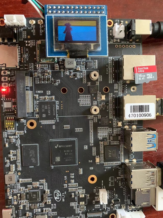
spi ssd1306 oled example
root@bananapif3:~/WiringPi# cd examples
root@bananapif3:~/WiringPi/examples# make oled
root@bananapif3:~/WiringPi/examples# ./oled
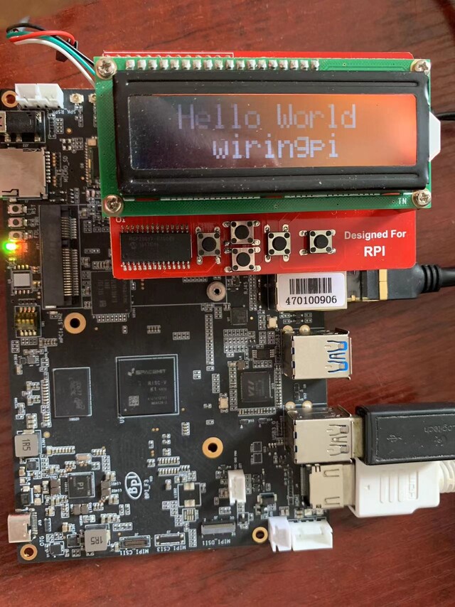
i2c lcd1602 oled example
root@bananapif3:~/WiringPi# cd examples
root@bananapif3:~/WiringPi/examples# make lcd-adafruit
root@bananapif3:~/WiringPi/examples# ./lcd-adafruit 3
Libgpiod
libgpiod is a library specifically designed for interacting with the Linux GPIO subsystem, offering a more modern and efficient way compared to the traditional sysfs interface. It also provides several command-line tools for controlling GPIOs.
Installing gpiod packages
root@bananapif3:~# sudo apt -y install gpiod libgpiod-dev
gpiodetect - get gpiochip list
root@bananapif3:~# gpiodetect
gpiochip0 [k1x-gpio] (128 lines)
gpiochip1 [spacemit-pinctrl@spm8821] (6 lines)
gpioinfo - get all gpio pins, 128 lines corresponding to 128 GPIOs, line number is gpio number.
root@bananapif3:~# gpioinfo
gpiochip0 - 128 lines:

	      line   0: "GMAC0_RXDV"       unused   input  active-high
	      line   1: "GMAC0_RXD0"       unused   input  active-high
	      line   2: "GMAC0_RXD1"       unused   input  active-high
	      line   3: "GMAC0_RXCLK"      unused   input  active-high
	      …
gpiochip1 - 6 lines:
	      line   0:      unnamed       unused  output  active-high
	      line   1:      unnamed       unused  output  active-high
	      line   2:      unnamed       unused  output  active-high
	      line   3:      unnamed       unused  output  active-high
	      …
gpioget - get gpio level, gpio 50 is 26pin phy pin.26
root@bananapif3:~# gpioget gpiochip0 50
1
gpioset - set gpio output level
root@bananapif3:~# gpioset gpiochip0 50=0
gpiomon - monitor GPIO event
root@bananapif3:~# gpiomon gpiochip0 50
(GPIO event output)
event: FALLING EDGE offset: 50 timestamp: [     647.533655138]
event: FALLING EDGE offset: 50 timestamp: [     647.533674597]
…
gpiofind - get 26pin phy pin.26 gpio number by gpio line name
root@bananapif3:~# gpiofind CON_P26
gpiochip0 50
Python3-libgpiod
python3-libgpiod is the Python binding library for libgpiod, which allows the use of libgpiod’s features to control and monitor GPIO pins in Python, only support gpio input/output control
Install python3-libgpiod
root@bananapif3:~# apt install python3-libgpiod
gpio_get.py, get gpio pin level
import gpiod

# 26pin, phy.26, gpio50
LINE_OFFSET = 50

# chip number and pin number
chip = gpiod.Chip("0", gpiod.Chip.OPEN_BY_NUMBER)
line = chip.get_line(LINE_OFFSET)

# input
line.request(consumer='gpio', type=gpiod.LINE_REQ_DIR_IN)

# get gpio level
value = line.get_value()
print(f"GPIO value is {value}")
gpio_set.py, set gpio output level
import gpiod

# 26pin, phy.26, gpio50
LINE_OFFSET = 50

# chip number and pin number
chip = gpiod.Chip('gpiochip0')
line = chip.get_line(LINE_OFFSET)

# output
line.request(consumer='example', type=gpiod.LINE_REQ_DIR_OUT)

# high level
line.set_value(1)
gpio_monitor.py, monitor gpio pin event
import gpiod

# 26pin, phy.26, gpio50
LINE_OFFSET = 50

# chip number and pin number
chip = gpiod.Chip('gpiochip0')
line = chip.get_line(LINE_OFFSET)

# request trigger type(rising and falling)
line.request(consumer='example', type=gpiod.LINE_REQ_EV_BOTH_EDGES)

print("Waiting for events...")
while True:
    event = line.event_wait(sec=5)
    if event:
        evt = line.event_read()
        if evt.type == gpiod.LineEvent.RISING_EDGE:
            print("Rising edge detected")
        elif evt.type == gpiod.LineEvent.FALLING_EDGE:
            print("Falling edge detected")
    else:
       print("No event detected in the last 5 seconds")
Python3-periphery
python3-periphery is a Python library used for controlling various hardware peripherals. It supports interaction with hardware interfaces like GPIO, I2C, SPI, serial (UART), and MMIO (memory-mapped I/O). The library is designed to provide a simple and consistent way to access these interfaces, allowing Python programs to easily control hardware devices.
Install python3-periphery
$ sudo apt install python3-periphery
gpio.py, gpio set and get test
from periphery import GPIO

# gpiochip0
CHIP = "/dev/gpiochip0"

# 26pin phy.7, gpio70
LINE_OFFSET = 70

# set output
gpio = GPIO(CHIP, LINE_OFFSET, "out")

# set high level
gpio.write(True)

# get gpio level
print("GPIO state:", gpio.read())

gpio.close()
i2c.py, read I2C device register test
enable 26pin phy pin.3 and pin.5 I2C4 functions before i2c test
from periphery import I2C

# i2c4, slave address 0x50
I2C_DEV = "/dev/i2c-4"
SLAVE_ADDR = 0x50

# intial i2c dev
i2c = I2C(I2C_DEV)

# read reg
msg = [I2C.Message([0x10]), I2C.Message([0x00], read=True)]
i2c.transfer(SLAVE_ADDR, msg)

print("I2C data read: 0x{:02x}".format(msg[1].data[0]))

i2c.close()
spi.py, spi loopback test, short connect 26pin,phy.19(SPI3_MOSI) and phy.21(SPI3_MISO)
enable 26pin phy pin.18, pin21, pin23, and pin.24 SPI3 functions before spi test
from periphery import SPI

# spi dev
SPI_DEV = "/dev/spidev3.0"

# send data
data_out = [0xAA, 0xBB, 0xCC, 0xDD]

try:
    # request spi,open spidev3.0,mode 0, freqency 1MHz
    spi = SPI(SPI_DEV, 0, 1000000)

    # send data and receive data
    data_in = spi.transfer(data_out)

    print("send: [0x{:02x}, 0x{:02x}, 0x{:02x}, 0x{:02x}]".format(*data_out))
    print("receive: [0x{:02x}, 0x{:02x}, 0x{:02x}, 0x{:02x}]".format(*data_in))
finally:
    spi.close()
uart.py, uart read and write test
enable 26pin phy pin.7, and pin.11 UART5 functions before uart test
from periphery import Serial

# uart device and baudrate
UART_DEV = "/dev/ttyS4"
BAUDRATE = 115200

# initial uart
serial = Serial(UART_DEV, BAUDRATE)

# send data
serial.write(b"Hello, World!\n")

# receive data
data = serial.read(128)  # 读取最多128字节

print("Received:", data)

serial.close()
pwm.py, pwm test
enable 26pin phy pin.18 PWM7 functions before pwm test
from periphery import PWM
import time

# PWM7, pwmchip0, channel 0 ,26pin, phy.18, pwm7(0xd401bc00)
PWM_CHIP = 0
PWM_CH = 0

# initial pwm
pwm = PWM(PWM_CHIP, PWM_CH)

# 2500Hz ( period_ns limit to 400000ns)
pwm.frequency = 2500

# duty 50% percentage
pwm.duty_cycle = 0.5

# set period_ns 20,000 ns
# pwm.period_ns = 20000

# set duty_cycle_ns 10,000 ns (50%)
# pwm.duty_cycle_ns = 10000

# enable pwm
pwm.enable()

time.sleep(5)

# set 10% percentage
pwm.duty_cycle = 0.1

# set duty_cycle_ns 2000ns (10%)
# pwm.duty_cycle_ns = 2000

time.sleep(5)

# disable pwm
pwm.disable()

# unexport PWM
pwm.close()
Adafruit Blinka
Adafruit Blinka is similar to python-periphery in functionality, providing control over GPIO, I2C, SPI, PWM, and UART interfaces. More info please ref to Adafruit wiki and adafruit github
Install packages
root@bananapif3:~# apt install git gpiod python3-dev python3-libgpiod python3-periphery python3-pip python3-venv libjpeg-dev zlib1g-dev libfreetype-dev libfreetype6 fonts-dejavu
Install Adafruit Blinka locally from PyPI.
root@bananapif3:~# pip3 install Adafruit-Blinka
Install Adafruit Blinka from git source
root@bananapif3:~# pip3 install git+https://github.com/adafruit/Adafruit_Blinka
To install in a virtual environment in your current project:
oot@bananapif3:~# mkdir project-name
root@bananapif3:~# cd project-name
root@bananapif3:~# python3 -m venv myenv
root@bananapif3:~# source myenv/bin/activate
(myenv) root@bananapif3:~#
Install gpiod python binding library
(myenv) root@bananapif3:~# pip3 install gpiod
virtual env Install Adafruit Blinka from PyPI.
(myenv) root@bananapif3:~# pip3 install Adafruit-Blinka
virtual env Install Adafruit Blinka from git source
(myenv) root@bananapif3:~# pip3 install git+https://github.com/adafruit/Adafruit_Blinka
Blinka Test examples
create a new file called blinkatest.py with nano or your favorite text editor and put the following in:
import board
import digitalio
import busio

print("Hello, blinka!")

# pin.26, Try to create a Digital input
pin = digitalio.DigitalInOut(board.D26)
print("Digital IO ok!")

# Try to create an I2C device
i2c = busio.I2C(board.SCL, board.SDA)
print("I2C ok!")

# Try to create an SPI device
spi = busio.SPI(board.SCLK, board.MOSI, board.MISO)
print("SPI ok!")

print("done!")
Save it and run at the command line with:
(myenv) root@bananapif3:~# python3 blinkatest.py
Hello, blinka!
Digital IO ok!
I2C ok!
SPI ok!
done!
(myenv) root@bananapif3:~#
create blinka_led.py example that blinks the LED on and off once a second
import time
import board
import digitalio

print("hello blinky!")

# pin.26
led = digitalio.DigitalInOut(board.D26)
led.direction = digitalio.Direction.OUTPUT

while True:
    led.value = True
    time.sleep(0.5)
    led.value = False
    time.sleep(0.5)
create blinka_button example that control the led turns on whenever the button is pressed
import time
import board
import digitalio

print("press the button!")

# pin.26
led = digitalio.DigitalInOut(board.D26)
led.direction = digitalio.Direction.OUTPUT

button = digitalio.DigitalInOut(board.D22)
button.direction = digitalio.Direction.INPUT
button.pull = digitalio.Pull.UP

while True:
    led.value = not button.value # light when button is pressed!
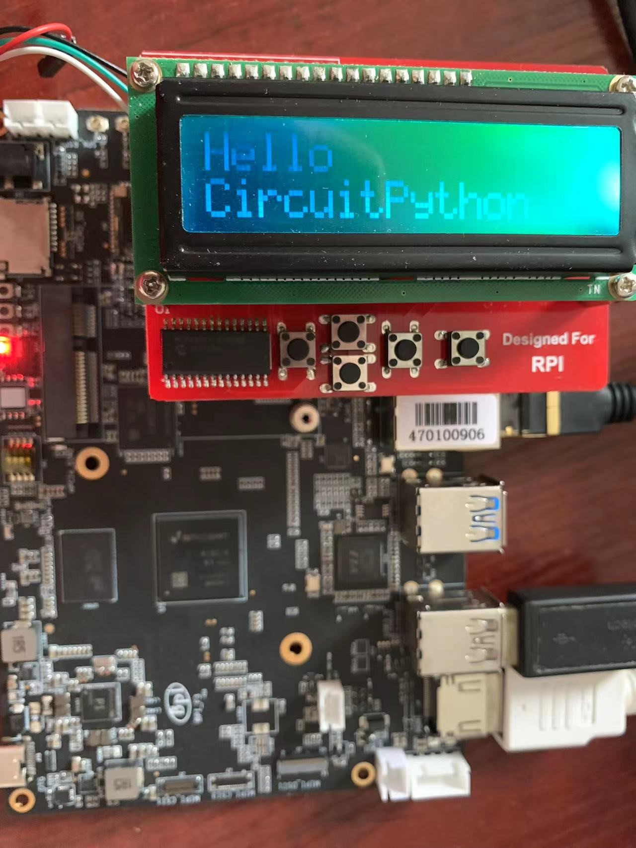
I2C rgb lcd test for MCP23017 I2C Lcd1602 Module
Installing libraries from git repo, these two repo forked from Adafruit_CircuitPython_CharLCD and Adafruit_CircuitPython_MCP230xx, modified to match the hardware MCP23017 I2C Lcd1602 Module. Examples in these two repo also should be modified to match the hardware design
(myenv) root@bananapif3:~# pip3 install git+https://github.com/Dangku/Adafruit_CircuitPython_CharLCD
(myenv) root@bananapif3:~# pip3 install git+https://github.com/Dangku/Adafruit_CircuitPython_MCP230xx
Running test example
(myenv) root@bananapif3:~# wget https://raw.githubusercontent.com/Dangku/Adafruit_CircuitPython_CharLCD/main/examples/charlcd_i2c_rgb_simpletest.py
(myenv) root@bananapif3:~# python3 charlcd_i2c_rgb_simpletest.py
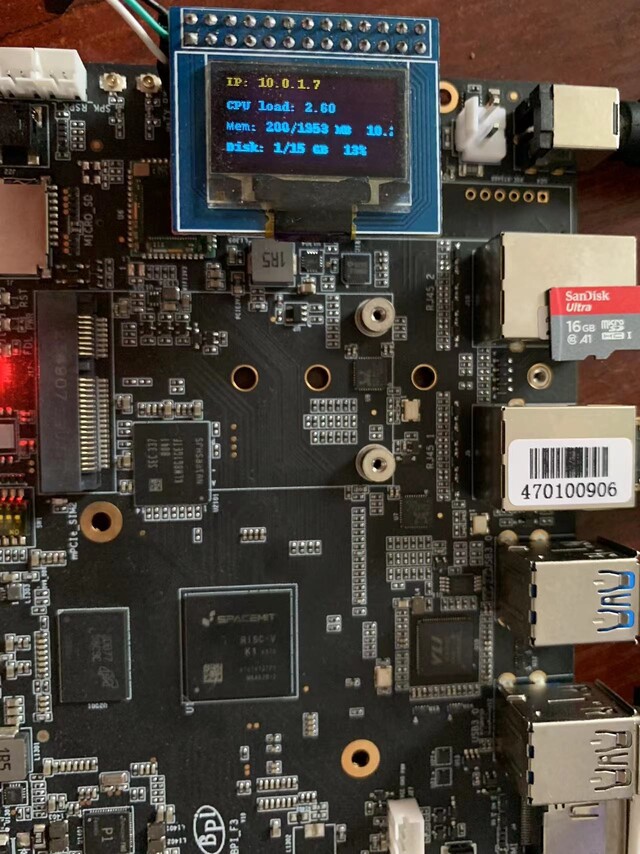
SPI oled test for SSD1306 SPI Oled Module
Installing the library from git repo, this repo forked from Adafruit_CircuitPython_SSD1306, libs and examples modified to match the hardware SSD1306 SPI Oled Module.
(myenv) root@bananapif3:~# pip3 install git+https://github.com/Dangku/Adafruit_CircuitPython_SSD1306
Installing pillow for some examples which import PIL, pip3 install Pillow command causes
ImportError: cannot import name ‘_imagingft’ from ‘PIL’, so instead with the following command.
(myenv) root@bananapif3:~# pip3 install Pillow --no-binary :all:
Running test example
(myenv) root@bananapif3:~# wget https://raw.githubusercontent.com/Dangku/Adafruit_CircuitPython_SSD1306/main/examples/ssd1306_stats.py
(myenv) root@bananapif3:~# python3 ssd1306_stats.py
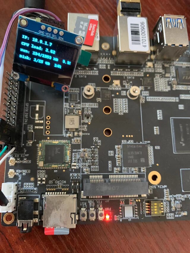
I2C oled test for SSD1306 I2C Oled Module
lib and examples source files are the same as spi ssd1306, but example must be modified to enable i2c interface and disable spi interface
# Create the I2C interface.
i2c = board.I2C()

# Create the SSD1306 OLED class.
# The first two parameters are the pixel width and pixel height.  Change these
# to the right size for your display!
disp = adafruit_ssd1306.SSD1306_I2C(WIDTH, HEIGHT, i2c)

# Use for SPI
#spi = board.SPI()
# disp_cs = digitalio.DigitalInOut(board.CS)
#disp_cs = None
#disp_dc = digitalio.DigitalInOut(board.D18)
#disp_reset = digitalio.DigitalInOut(board.D22)
#disp = adafruit_ssd1306.SSD1306_SPI(WIDTH, HEIGHT, spi, disp_dc, disp_reset, dii
sp_cs)
Running test example
(myenv) root@bananapif3:~# python3 ssd1306_stats.py
Luma.examples
luma.examples is a companion repo for running examples against the luma.oled, luma.lcd, luma.led_matrix and luma.emulator display drivers.
Install packages
root@bananapif3:~# apt-get install libsdl2-dev libsdl2-ttf-dev libsdl2-mixer-dev libsdl2-image-dev
Running in virtual environment created before
root@bananapif3:~# source myenv/bin/activate
(myenv) root@bananapif3:~#
Install RPi.GPIO from git repo
(myenv) root@bananapif3:~# pip3 install git+https://github.com/Dangku/RPi.GPIO.git
Clone Luma.examples and install libs
(myenv) root@bananapif3:~# git clone https://github.com/rm-hull/luma.examples.git
(myenv) root@bananapif3:~# cd luma.examples
(myenv) root@bananapif3:~# pip3 install -e .
Confirm packages installed successfully
(myenv) root@bananapif3:~# pip3 list | grep luma
luma.core                                2.4.2
luma.emulator                            1.5.0
luma.lcd                                 2.11.0
luma.led-matrix                          1.7.1
luma.oled                                3.13.0
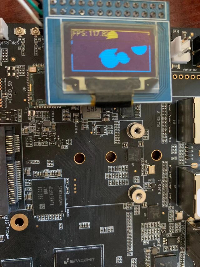
i2c ssd1306 oled test
create conf/ssd1306_i2c.conf, i2c device is /dev/i2c-4
--display=ssd1306
--interface=i2c
--i2c-port=4
--i2c-address=0x3C
--width=128
--height=64

(myenv) root@bananapif3:~# cd examples
(myenv) root@bananapif3:~# python3 bounce.py --config ../conf/ssd1306_i2c.conf
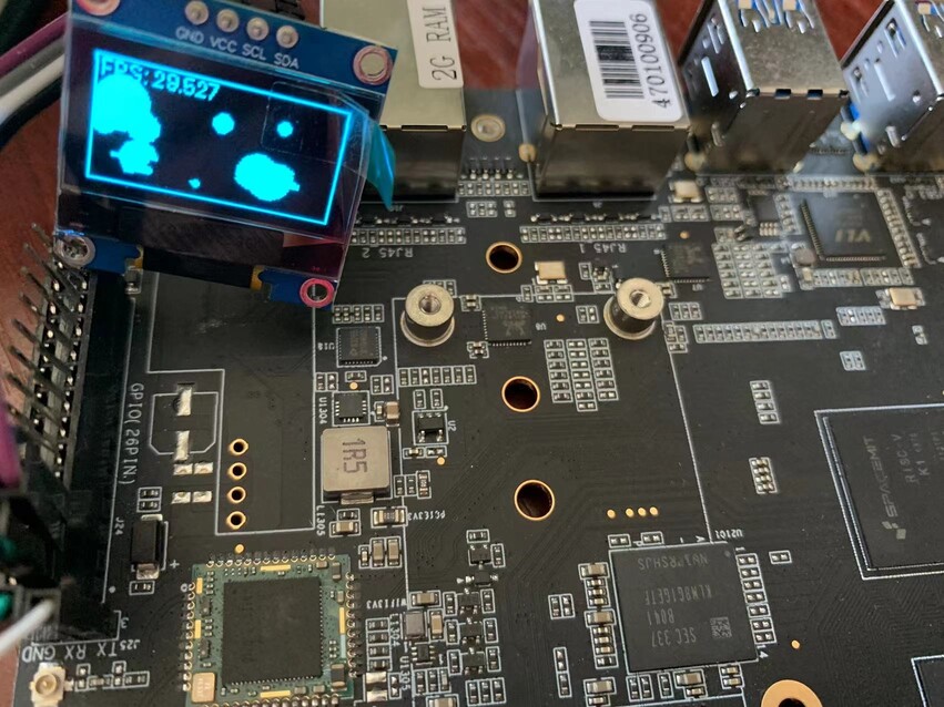
spi ssd1306 oled test
create conf/ssd1306_spi.conf, spi device is /dev/spi3.0
--display=ssd1306
--interface=spi
--spi-port=3
--spi-device=0
--spi-bus-speed=52000000
--width=128
--height=64

(myenv) root@bananapif3:~# cd examples
(myenv) root@bananapif3:~# python3 bounce.py --config ../conf/ssd1306_spi.conf
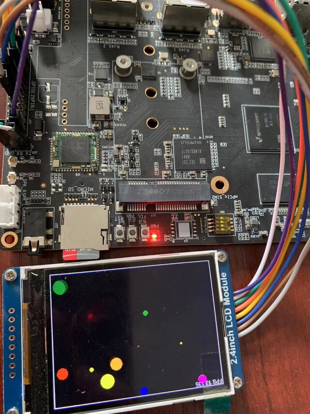
spi ili9341 lcd test
create conf/ili9341.conf, spi device is /dev/spi3.0, gpio-reset is phy pin.18, gpio-dc is phy pin.16, gpio-backlight is phy pin.12
--display=ili9341
--interface=spi
--spi-port=3
--spi-device=0
--spi-bus-speed=52000000
--gpio-reset=24
--gpio-data-command=23
--gpio-backlight=18
--width=320
--height=240
--backlight-active=high
--gpio-reset-hold-time=0.1
--gpio-reset-release-time=0.1

(myenv) root@bananapif3:~# cd examples
(myenv) root@bananapif3:~# python3 bounce.py --config ../conf/ili9341.conf