Maybe perforated punchouts or even slottable aluminium 4x antenna holes on each side?
As others have mentioned, a 1U form factor would be great but it could offer a lot of flexibility with that space - with clever screw placement, there could be options of 1, 2 or more mainboards with PSU external or internal. Depending on appetite, daughter boards could be added with capabilities for more PCIe for WiFi, NVMe, SFP, LAN or LTE.
Cooling is also worth consideration - needs thought on where to place fans and heatsinks.
Of course, interference testing is a must for a WiFi product.
This would fit a wide variety of use cases in that form factor.
Good afternoon @sinovoip, it would also be nice if the bottom cover had ventilation holes to accommodate this type of ventilation for routers. I’m sure that for those who aren’t bothered by the noise, the whole banana will be completely cool.
And some holes in the top to let air out. To make it look nicer, we could put a dust cover on top, like those used on magnetic PCs, to hide any ventilation holes that the top would have.
Looks nice but i would put the fans to the corners. Left one to front and other to back corner to get an airflow something like this | / |. Or make it possible to put two on both sides. But to be hones, this are not real facts from my side, just thinking about it cause i made a lot of cooling experiments with the bpi4 default case i like the space, could you tell us the dimensions? Cause i would love to put my zigbee and bluetooth usb dongle somehow inside the case The possibility for a dust cover for the fans would also be a special thing i’ve made myself for now
However, looks great, for the antenna positions i am also not sure if this is the best. For me a nicer approach would be to put them on the same side like the ethernet connectors. Or on the side. (maybe at all sides like at the “default” case. you can leave them open if you want some more air or “close” with an empty antenna plug like i did)
Good morning @sinovoip, are you finally reconsidering having the antennas on all four sides?
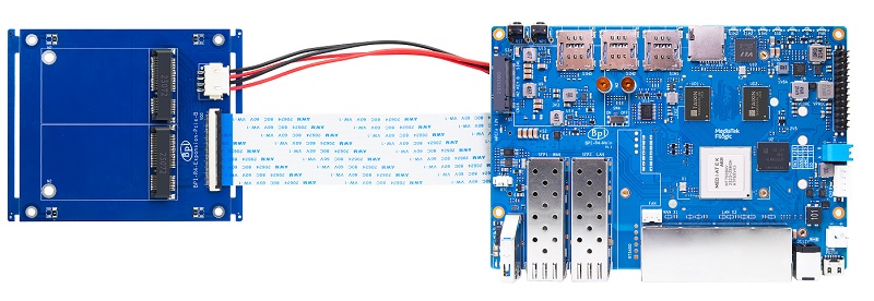
By having the BE14 separated, will it reduce noise and increase power?
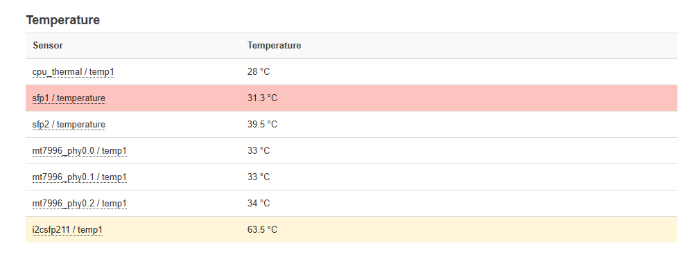
Currently, these are my temperatures. The highest is the 10GB SFP+RJ45 since I have 10GB symmetrical ports.
On 5GB, my temperature reaches 50 degrees, and on 2.5GB, 40 degrees. With the modifications I currently have, the pink one is the SFP+fiber XGS-PON WAS-110, which is magnificent.
Have you taken the temperatures into account, especially the 10GB SFP+RJ 45?
The rest of the antenna and CPU thermal temperatures.
The position of the antenna can be placed on both sides, freely chosen. Our actual test, put on one side has little effect. There will be antenna lines on both sides of the shell spare holes, if not used it, can be used as heat dissipation
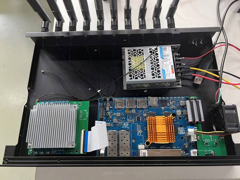
Good morning @sinovoip@simon, I currently have a 35x35x10 fan on both the SFP+ and the RJ-45 ports.
I’m so glad you have the BE19000 design. Let’s see how it works. I know @simon you’re in charge of this project, since I’ve been following you, and when you finish a couple of projects, you’ll probably go back to the BE19000. But if you confirm both, that’s great news.
I’m eagerly awaiting the new case and the BE19000.
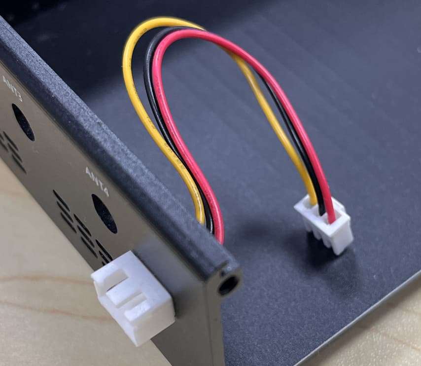
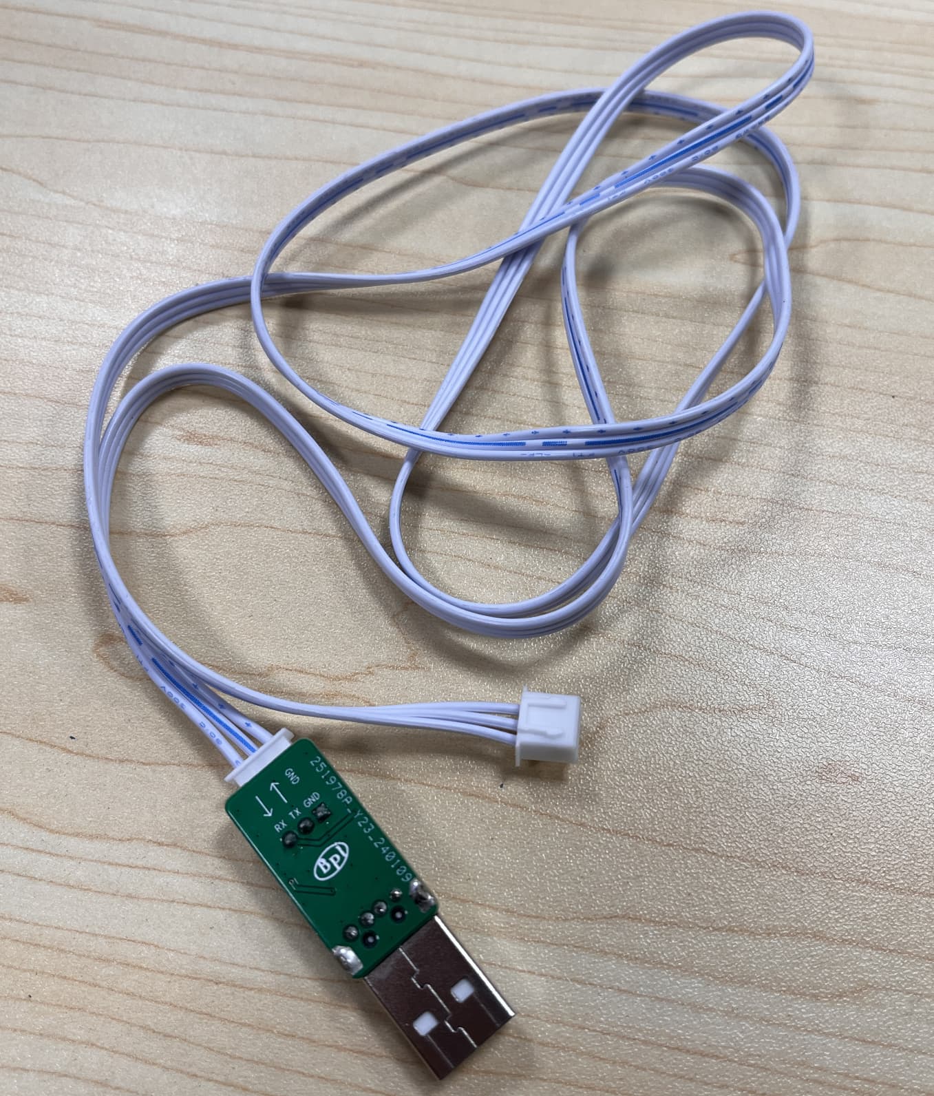
Sorry, UART, has it been taken into account to be able to use it externally?
Good morning @simon, I mean, has it been considered to put the UART externally so we can communicate with the board?
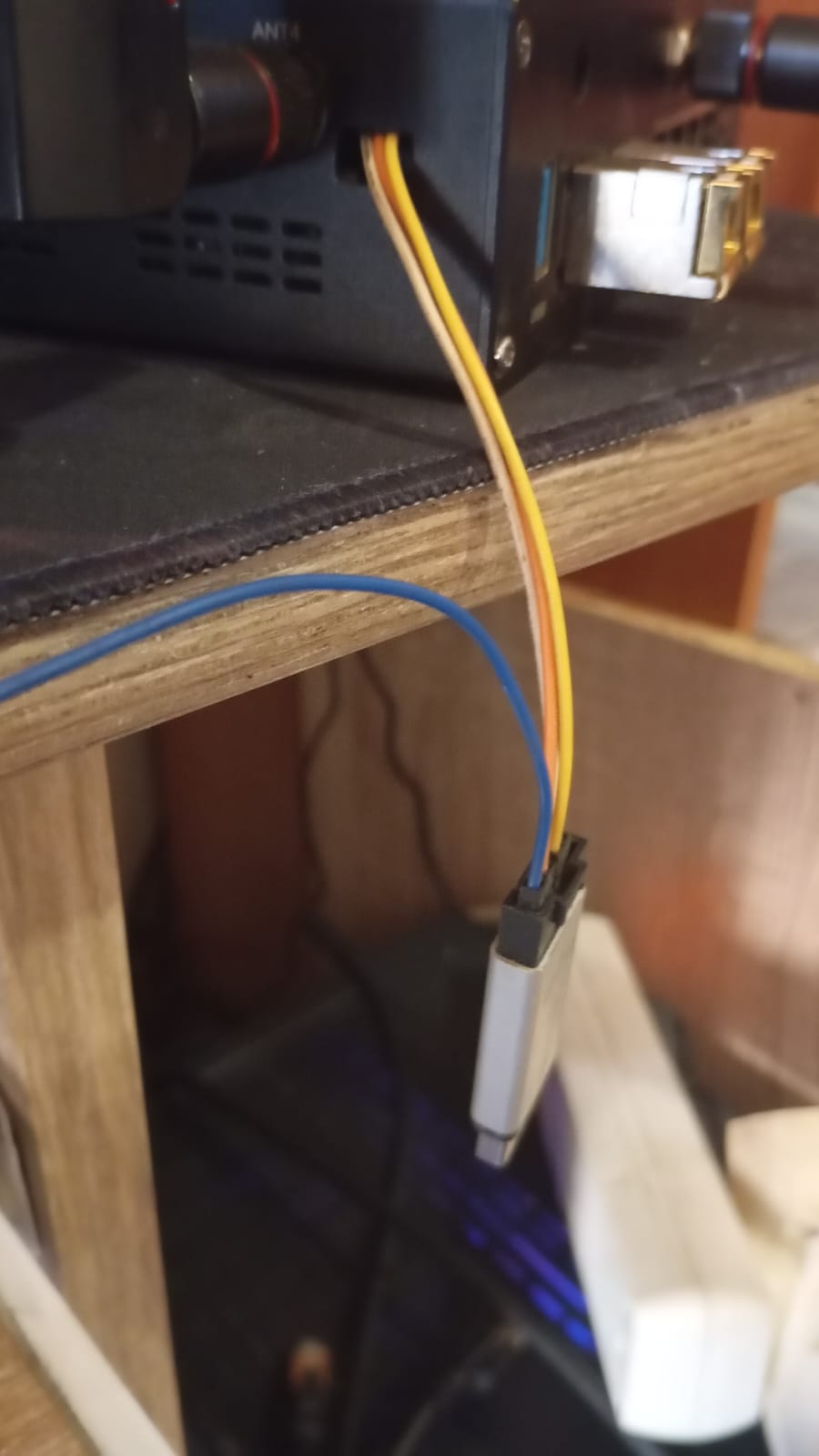
I currently have it like the photo, but I don’t see how to put it on the box if there’s no output for them. I’ve seen people modifying it, but I don’t know if it’s exactly this way so we can have it externally.
Good afternoon @simon@sinovoip, could you please let us know how production is going for the new box, and for the be19000, if it will be released at the end of this month or by the end of June, or maybe earlier?
The image @simon be19000 will be released with 21.02. There will also be a variant for 24.10 in the first release.