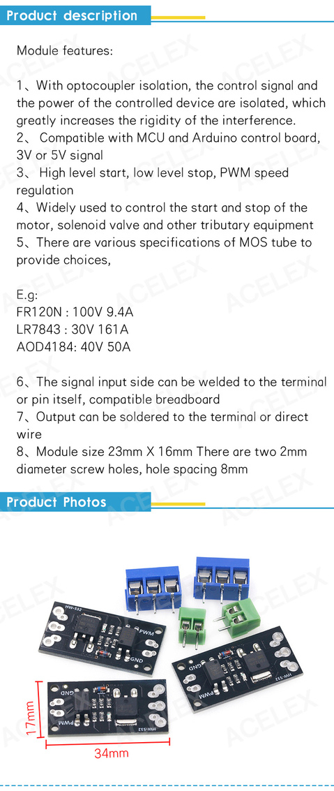
Why not use a mosfet module on any of the available gpio pins on the gpio header? No need to solder on the board. Like this one, it is not very expensive:
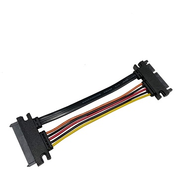
And get the 12V, soldering on a cable like this:
Why not use a mosfet module on any of the available gpio pins on the gpio header? No need to solder on the board. Like this one, it is not very expensive:

And get the 12V, soldering on a cable like this:

Thanks, I know I have many options to solve this problem with additional hardware/connectors, but I wanted to try a software solution.
All I need is a timer. I bet it can be done easily in kernel space.
Hello, this is my first post on this forum. I want to share my experience. I did some tests using small heatsinks on chips and the open case. I get the following readings from internal sensors in standby (no devices connected on WiFi) with a room temp of 20C:
phy0 2.4Ghz -> 68C phy1 5Ghz -> 43C
On the SoC the reading by internal sensor is 45C.
The temperatures detected with a thermal scanner (my bet was 3-4C low) are:
on 2.4Ghz -> 37.1C on 5Ghz -> 40.5C
On the Soc I get 45.5C.
It seems to me that the SW reading by sensor on 2.4Ghz chip is not so correct.
Please report this on
Is it possible to read temp of wifi-chips directly from sysfs?
Edit: found possible solution here
cat /sys/class/ieee80211/phy*/hwmon*/temp1_inputDone! I hope this can be checked.
First of all, thank you for the many helpful comments which helped me with my decisions.
In my setup, I deactivated the wifi chip by unloading the mt7915e module, because I don’t need it. This dropped the heat development a bit. I only use the Banana Pi as a gateway for my 1GBit fiber optic connection for netflow traffic analysis.
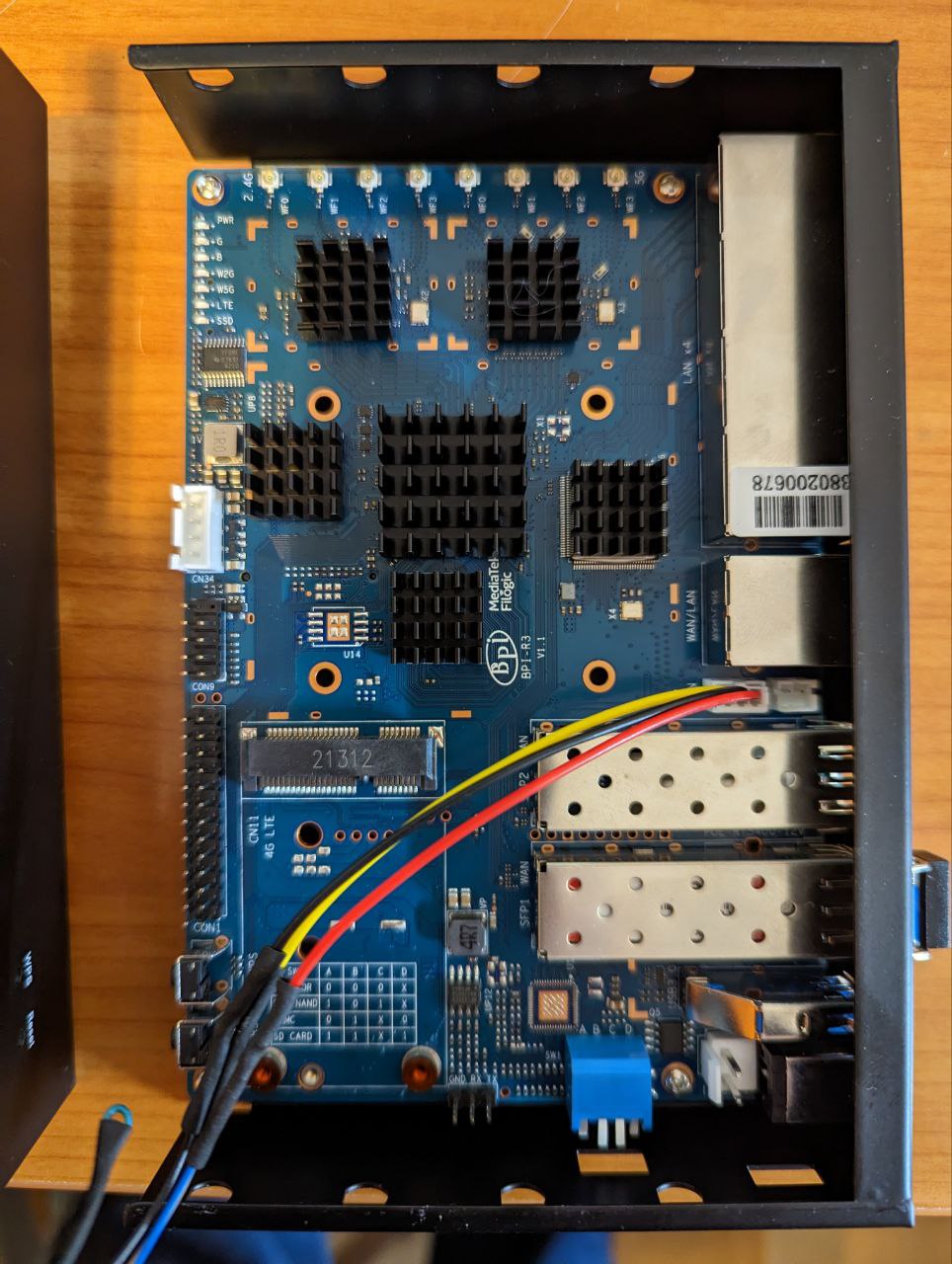
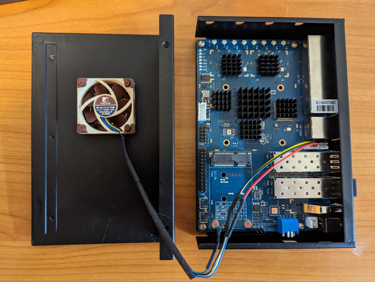
To do this, I glued individual heat sinks to each chip with thermally conductive adhesive. All packed in a metal case. Drilled a hole in the cover and inserted a 5V PWM fan.
This usually runs at the lowest inaudible speed and is controlled by pwm. The temperature of the CPU is 26°C in a performance/stress test and the SFP connector is 36°C.
here is my part list:
Metal case: https://de.aliexpress.com/item/1005004885309544.html
SFP Transceiver Modul: https://www.fs.com/de/products/20140.html
Heat Sink: https://amzn.to/3j1ojQy
Fan grille: https://amzn.to/3Xrec6R
Thermal adhesive: https://www.webshop-innovatek.de/waermeleitmittel/waermeleitkleber/701/high-silver-waermeleitkleber-2x-4-g?number=501909-01
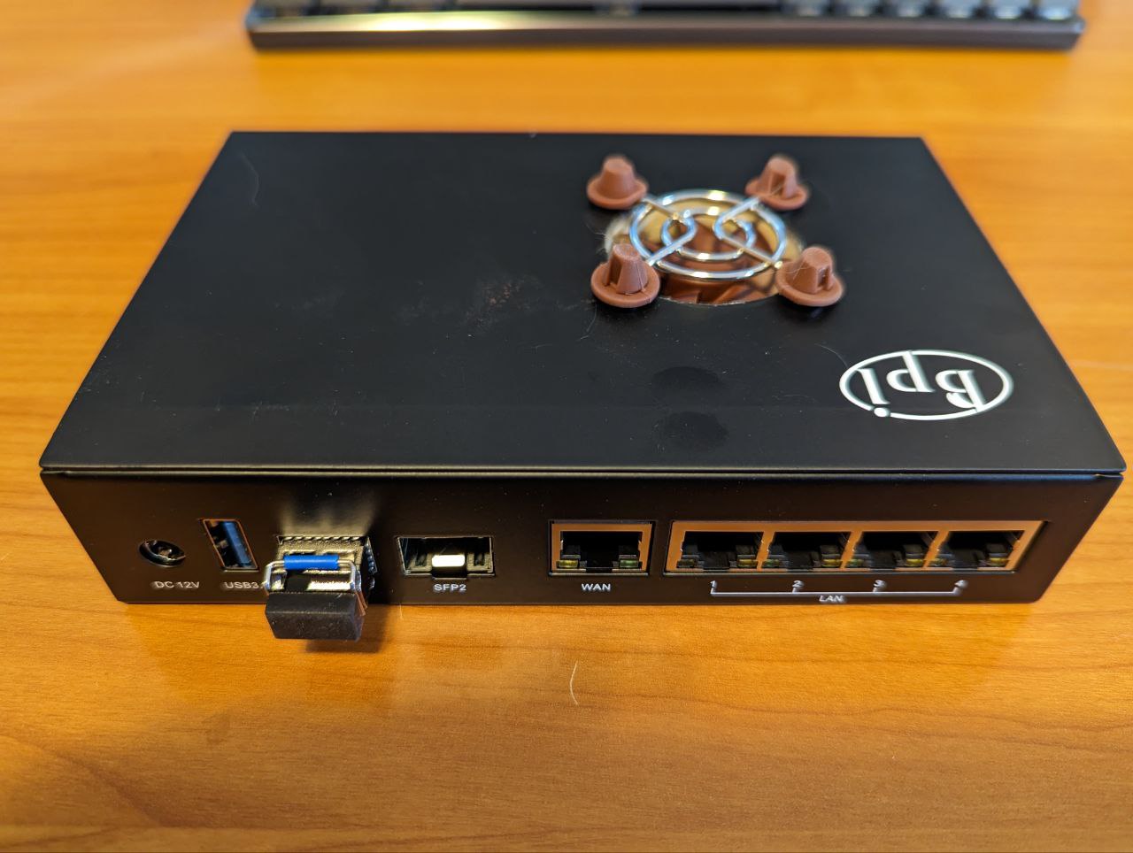
What is the OS? I have also 5V Noctua with PWM and the fan runs for just 5 second during boot and stops after that. What is the reason about that? Thank you.
i guess your board does not reach the temperature where fan is activated 
to activate pwm, you have to call
echo 1 > /sys/class/thermal/cooling_device0/cur_state
and my OS is lates openwrt trunk… but it does not matter for pwm.
That’s the answer I was looking for. Thank you!
Possible hw improvement would be adding a switch like bootswitches in v1.0 for R317/R318 to select fan voltage without soldering.
@sinovoip is this possible?
I’ve only seen heatsinks with fan and 43mm hole pitch using a 12v fan…no 5v fan. Ordered 2 5v pwm fans and heatsinks without holes to drill holes and cut a thread.
I just ordered the Noctua. I’m contemplating to buy a northbridge heat sink and remove the fan to screw the Noctua on the heatsink, if it does not work I’ll do your setup.
If I do that, what is the diameter of the hole you pierced in the case for the fan, and what is the bit size for the drill for the screw holes?
I have a 40x40mm fan,drilled a 36mm hole for fan and 3mm for the screws
I did something similar. I have mounted a heatsink of about 60x70mm, drilled a 28mm hole on the case and put a 30mm 5v fan in it. The temperature is now about 33 degrees Celsius (with the room at 20 degrees). I have now ordered a second BPI-R3 and I think I will do something similar for the fan but will probably use small single chip heatsinks.
I just received the Noctua PWM. There are 4 wires on the fan, 3 on the board. I see that you selected one of the 2 blue wires. Does it matter which one you take?
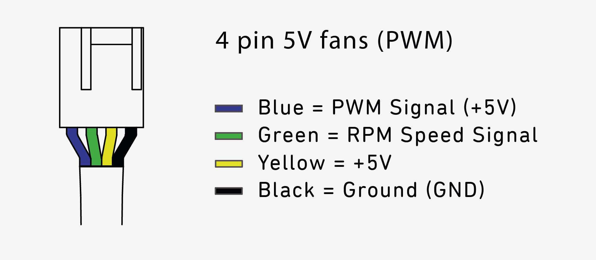
it is the green one, you don’t need.
but before you finally cut the cable, test it 
What is the best way to persist this after reboot?
I confirm this. I have
sensors
mt7915_phy1-isa-18000000
Adapter: ISA adapter
temp1:        +63.0°C  (high = +120.0°C, crit = +110.0°C)

mt7915_phy0-isa-18000000
Adapter: ISA adapter
temp1:        +41.0°C  (high = +120.0°C, crit = +110.0°C)
With my thermometer gun, I read 40C max.