Thanks, but I wouldn’t need the script if I were using the pwm interface, but instead I’m using the SATA 12v pin by driving GPIO8
So you can change that easily in the DTS as well and assign pwm1 instead of pwm0 here:
Set this instead
pwms = <&pwm 1 10000 0>;
ok that’s interesting, I thought about doing something like that, but I assumed it would be more complicated. How do I define the new pwm pin in pwm_pins? I’m not familiar with dts syntax… thank you! I want to use GPIO8
pwm_pins already selects GPIO_21 for pwm0 (the fan connector) and GPIO_22 (pin 7 on the GPIO header). This is why your shell script works with with pwm1 in first place. So no need to change anything there. Anyway you can not use any other pins as PWM with this board.
That’s a shame… My script simply sets GPIO8 high/low and that sets the SATA 12v on/off. But I do have another script which actually generates PWM using core-utils sleep #!/bin/sh
function gpiopwm() {
    sleep_low=$(awk -v freq="$2" -v duty="$3"  'BEGIN{print (1/freq)*((100-duty)/100)}')
    sleep_high=$(awk -v freq="$2" -v duty="$3"  'BEGIN{print (1/freq)*((100-(100-duty))/100)}')
    echo "low $sleep_low high $sleep_high"
    var_count=0
    repeat=1000
    while [ $var_count -lt $repeat ]
    do
    echo 1 > /sys/class/gpio/gpio$1/value
    sleep $sleep_high
    echo 0 > /sys/class/gpio/gpio$1/value
    let var_count=var_count+1
    if [ $var_count -le $repeat ]
    then
            sleep $sleep_low
    fi
    done
}

echo 419 > /sys/class/gpio/export
echo out > /sys/class/gpio/gpio419/direction
lastcpu=0
duty=15
gpiopwm 419 20 10
echo "finished 10"
gpiopwm 419 20 90
Already tested, It works great. The frequency is not that high . All you have to do is to connect the SATA 12V to the fan VCC, no need to connect anything to the pwm input
Hallo Dale,
yes of course NC! I should have seen this! Thanks 
I found R318 on the backside:
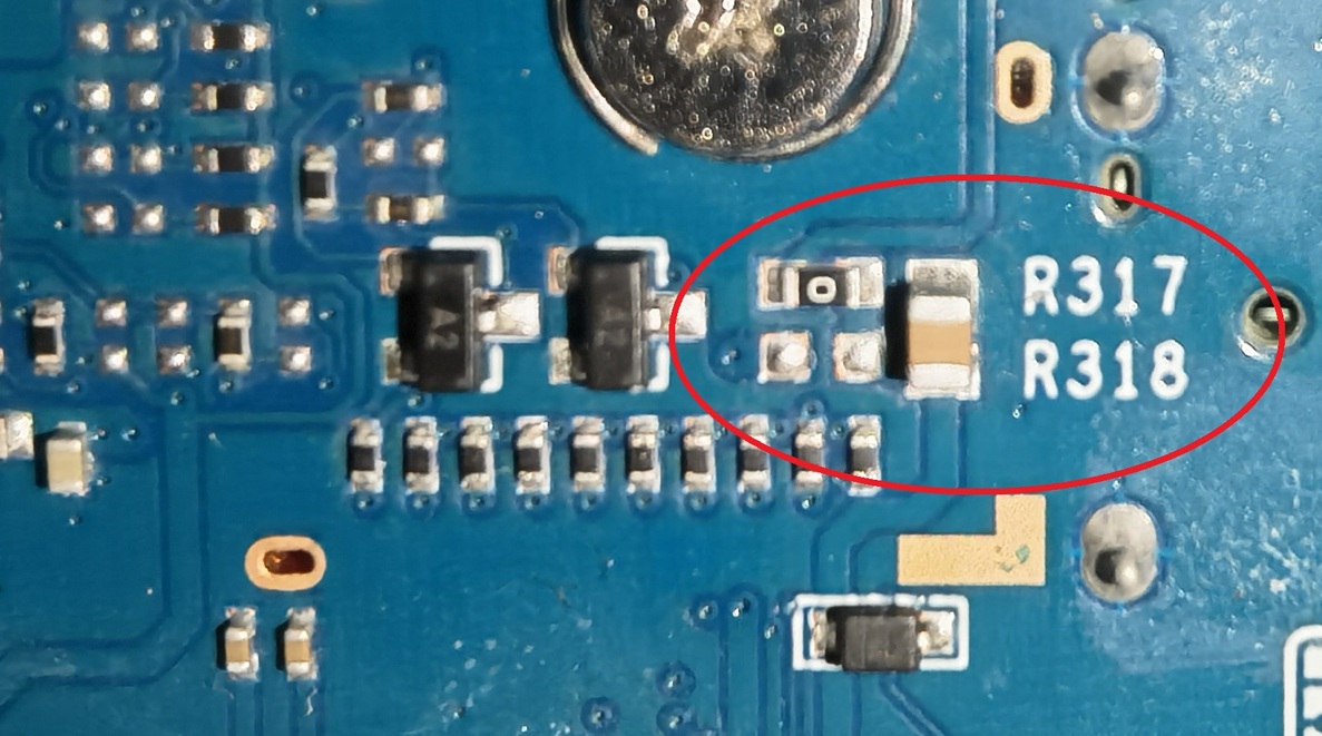
Next days, i will solder it. But before I have to gather some courage. 
1 Like
Just make sure you remove R317 first or else you will see fireworks
Hi AntonyFI
thanks for the “sensors”-command. Without you i could not check my W-Lan chip temperature!
What are you using for cooling? -> single heat sinks or one big heat sink?
I made a short overview:
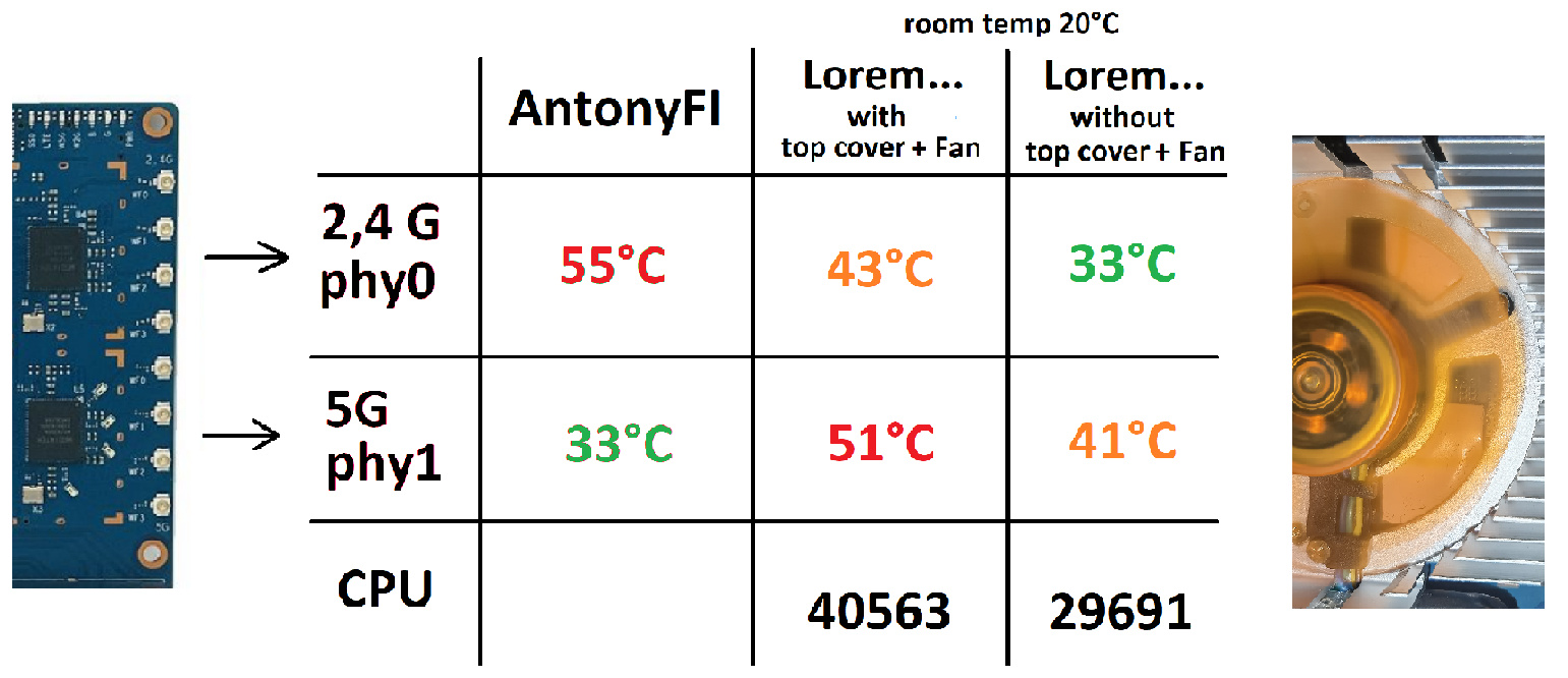
For my temperature deviation i have an explanation. This could be the bad placed holes in the metal heat sink. If the values are right the CPU temperature is lower than the W-Lan chip temps. 
But for your problem … i have no explanation.
If someone else has temp readout commands for the other chips (exept cpu and w-lan) -> I’m very interested!
All these context switching does affect the CPU. nothing serious but still… I rather do that in kernel space. @dangowrt , is it absolutely impossible to change the PWM pin to GPIO_8 using the dts? the alterative would be to write a simple kernel module
changing the pins in pinctrl-mt7986.c should work, right?
No the hardware only allows PWM0 to be assigned to pin 21 (PWM0), PWM1 can only be mapped to either pin 22 (PWM1) or pin 20 (GPIO_15):
The pinctrl-mt7986.c driver reflects the capabilities of the hardware, there is no point in making changes to this driver, it will not help you.
Why is it so important for you to be that specific pin?!
I see… It is indeed there in the reference manual. unfortunately I didn’t see in the manual any IO mux that could help me as well.
I want to use GPIO_8 because it’s the SATA_PWREN line that enables SATA_12V. it allows me to have a controllable 12v pin for the fan
Why not use a mosfet module on any of the available gpio pins on the gpio header? No need to solder on the board. Like this one, it is not very expensive:

And get the 12V, soldering on a cable like this:
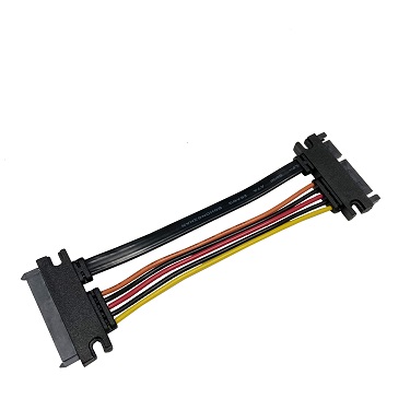
Thanks, I know I have many options to solve this problem with additional hardware/connectors, but I wanted to try a software solution.
All I need is a timer. I bet it can be done easily in kernel space.
Hello, this is my first post on this forum. I want to share my experience. I did some tests using small heatsinks on chips and the open case. I get the following readings from internal sensors in standby (no devices connected on WiFi) with a room temp of 20C:
phy0 2.4Ghz -> 68C phy1 5Ghz -> 43C
On the SoC the reading by internal sensor is 45C.
The temperatures detected with a thermal scanner (my bet was 3-4C low) are:
on 2.4Ghz -> 37.1C on 5Ghz -> 40.5C
On the Soc I get 45.5C.
It seems to me that the SW reading by sensor on 2.4Ghz chip is not so correct.
Please report this on
Is it possible to read temp of wifi-chips directly from sysfs?
Edit: found possible solution here
cat /sys/class/ieee80211/phy*/hwmon*/temp1_inputDone! I hope this can be checked.
First of all, thank you for the many helpful comments which helped me with my decisions.
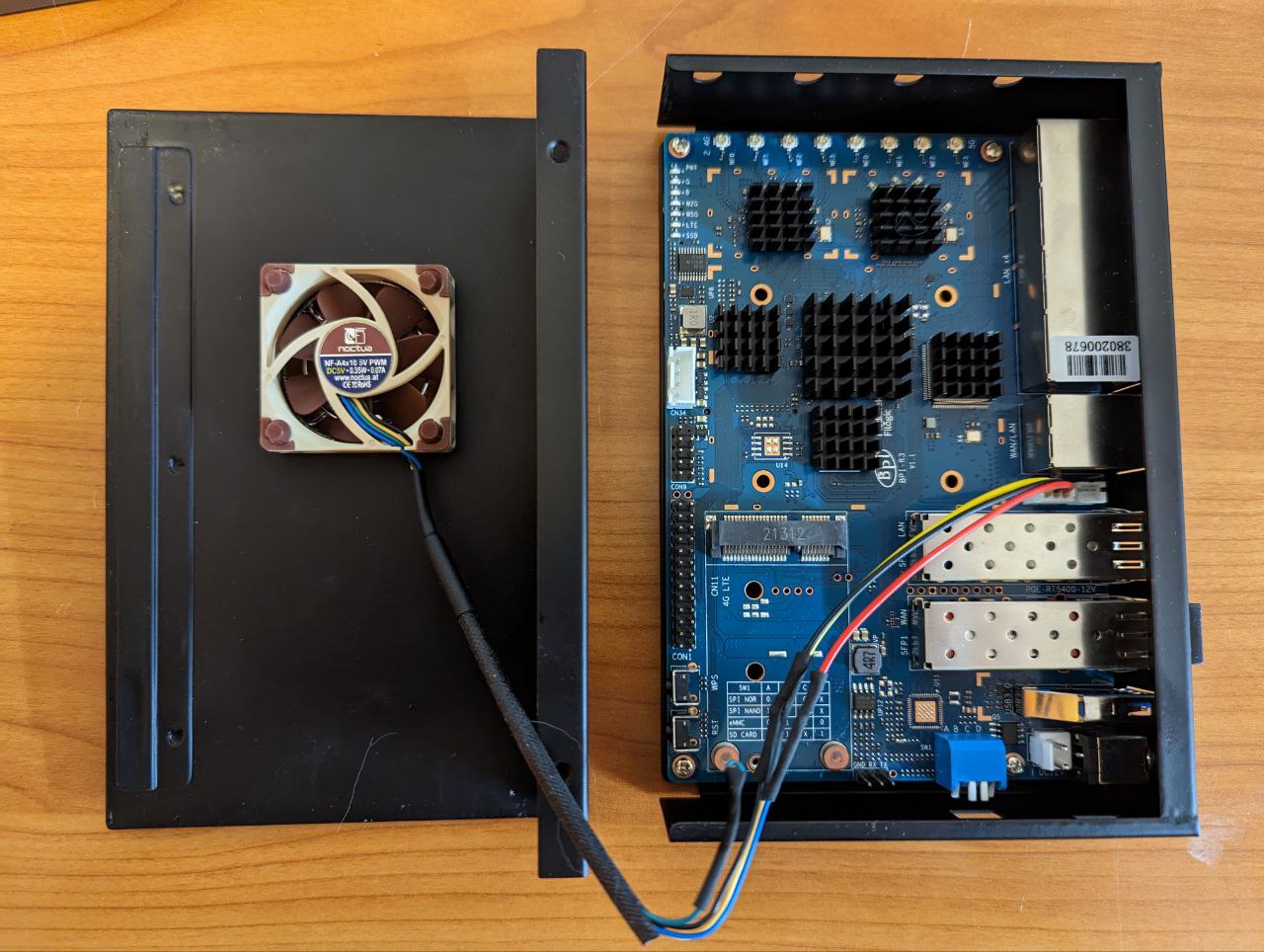
In my setup, I deactivated the wifi chip by unloading the mt7915e module, because I don’t need it. This dropped the heat development a bit. I only use the Banana Pi as a gateway for my 1GBit fiber optic connection for netflow traffic analysis.
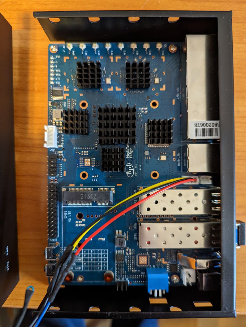
To do this, I glued individual heat sinks to each chip with thermally conductive adhesive. All packed in a metal case. Drilled a hole in the cover and inserted a 5V PWM fan.
This usually runs at the lowest inaudible speed and is controlled by pwm. The temperature of the CPU is 26°C in a performance/stress test and the SFP connector is 36°C.
here is my part list:
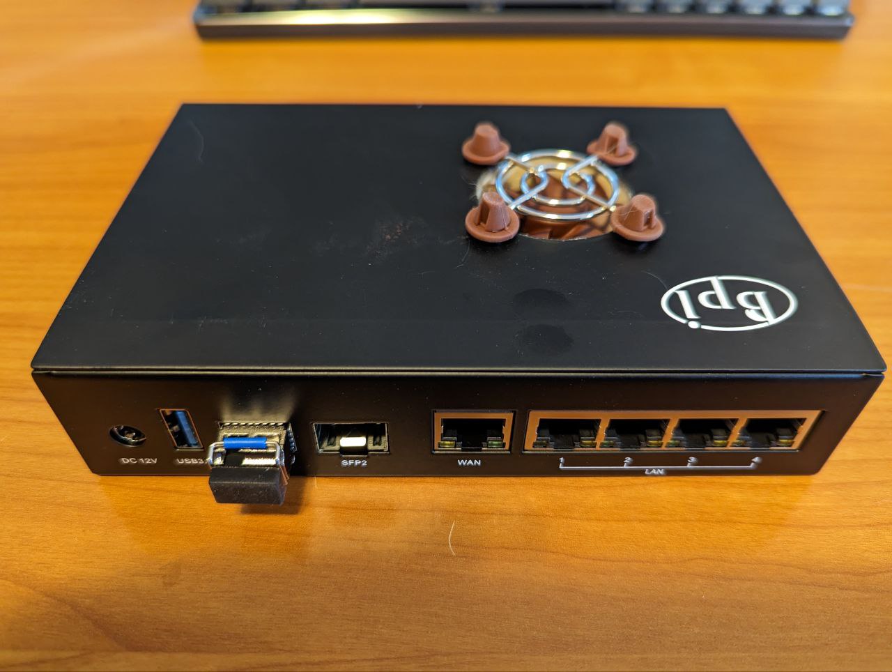
Metal case: https://de.aliexpress.com/item/1005004885309544.html
SFP Transceiver Modul: https://www.fs.com/de/products/20140.html
Heat Sink: https://amzn.to/3j1ojQy
Fan grille: https://amzn.to/3Xrec6R
Thermal adhesive: https://www.webshop-innovatek.de/waermeleitmittel/waermeleitkleber/701/high-silver-waermeleitkleber-2x-4-g?number=501909-01
4 Likes
What is the OS? I have also 5V Noctua with PWM and the fan runs for just 5 second during boot and stops after that. What is the reason about that? Thank you.