Banana pi R3 fan with PWM

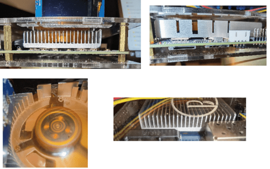
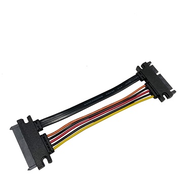
I connected the 4 pin fan to the sata connector, using this script to control the fan usage

#!/bin/sh

pin_num=8
sleep_time=5 #seconds
fan_time=30 #seconds
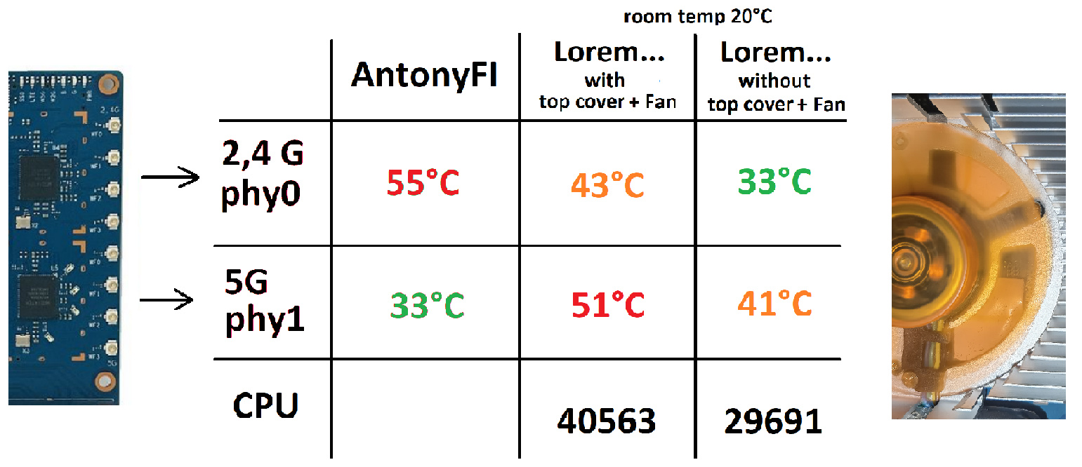
fan_temp_threshold=45

gpio_num=$((pin_num + 411))
echo $gpio_num > /sys/class/gpio/export
gpio_sys_path='/sys/class/gpio/gpio'
gpio_sys_path="${gpio_sys_path}${gpio_num}"
current_dir="`cat ${gpio_sys_path}/direction`"
if [ "$current_dir" = "in" ]; then
	echo out > "${gpio_sys_path}"/direction
fi
echo 0 > ${gpio_sys_path}/value
while [ true ]
do
temp=$((`cat /sys/class/thermal/thermal_zone0/temp`/1000))
if [ "$temp" -gt "$fan_temp_threshold" ]; then
	echo 1 > ${gpio_sys_path}/value
	sleep $fan_time
	echo 0 > ${gpio_sys_path}/value
else
	sleep $sleep_time
fi
done

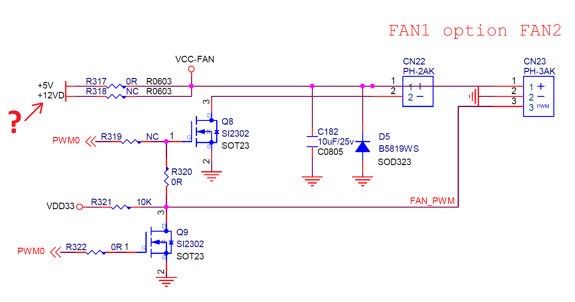
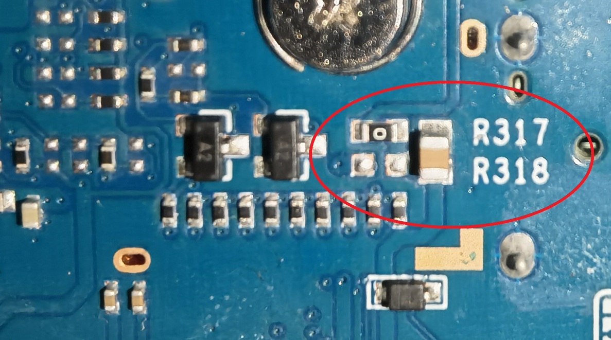
You can also use GPIO8 to generate a 12v PWM signal. I have a script for that as well if anyone is interested. You only need 2 wires.

have you measured the thickness of thermalpad? currently i have only 1mm at home, need to order 0.5 and 1.5mm

Hi frank, first I have to say, I did not made a professional measurement!

After I had access to the board, I took a ruler and looked at the height ratio of the different chips. The chips with green point looked similar.

I ordered 1x 0.5 mm pad and 1x 1.0 mm pad (I know it’s expensive). → First try was 0.5 mm (orange) and the others 1.0 mm (green). But there was a visible inequality. 1.0 mm was too less. → So, I took the 0.5 mm pads and do them additionally on the 1.0 mm pads. → At the end it was 0.5 mm (orange) and 1.5 mm (green)

The problem is, that the main-target is to cool the processor in the middle. But there is no visible proof that the pad has 100% contact with this chip. This is why I take the “soft” variant of this EC360 pads. I think it was a good choice. My basic tests show a quick temperature change after i removed the top cover (I did not jet made a hole for the fan in the top cover). I now, this is not a direct proof. But a good start :slightly_smiling_face:.

Heat%20Sink

So, if you have enough 1.0 mm you will only need an additional 0.5 mm :ok_hand: .

!!! I forgot an important detail:

I take away ca.1 mm of the screw sleeve on the backside of the heat sink.

fan

I filed this away with a rasp. It was just a prevention to make sure that there would be no space between the heat sink and thermal pad. But this also means you have to be very careful during tighten the screws.

I simply put thermal paste on the chips. Using my script, with case closed, the temperature drops from 51 to 46 in 30 seconds of fan work. So far the temperature never reach the script limit unless i run a stress test. The average temperature is 46.

I’m not sure what is the best way …

I took the best thermal pad I could get. I was not thinking about thermal paste.

You can discuss this in different ways; -> Can you get a mechanical stress problem? -> If you have a bigger layer than normal, can the thermal paste still beat the 1.5 mm colling pad?

Heat_sink

I have really no answers on this questions.

At the start of this project, I didn’t expect that only the cooling would have so much solutions. I was also thinking about passive cooling with single heat sinks on every chip. We see this solution in this chat. May be this is enough? Or with a bigger fan on the whole Board. Yesterday I started the first tests with SFP-Modules and without any established connection I had 1W more power consumption. Some manufacturers have passive heat sinks one the SFP modules. And with LTE running in a closed case it could may keep my tea warm?

I also see how limited we are. If I look at my cooling solution (heat sink + fan), than I see on the right side and left side are chips not 100% covered. Even the W-Lan chips are not perfect covered. And after installing heat sink there is not much space for the W-Lan antenna cables. But every other solution would be very time consuming.

I have not started may case project, but I will be significantly influenced by the heat topic.

I’m not an expert in schematic design but there should be is a 12V channel on the normal 3Pin and 2Pin fan supply? Is this right?:

12V%20Fan

I now, the explaining picture shows “5V”.

But currently I started the fan over Luci with: echo 1 > /sys/class/thermal/cooling_device0/cur_state

-> echo 3 and echo 2: only start the fan for a few seconds. After that, the fan turns off.

-> echo 0: stops the fan immediately

The interesting part for me is:

During the boot time the fan runs much faster than with echo 1.

After Luci starts the fan stops short, and echo 1 takes over.

The fan runs the whole time but not as fast as during the booting time.

I just started with Open WRT and I’m satisfied with Echo 1. But I ask myself, could it be the 12W? Or is something else going on (maybe PWM) …

R318 is NC (not connected), you could swap the resistors and then the fan voltage would be 12v. Passive cooling is enough with open case, but when the case is closed it might not. Especially in summer. My current setup is good enough for me. The script turns on the fan in case it gets too hot and I supply the fan with 12v as it should be. Since GPIO8 is connected to a 12v gate you could also generate a 12v PWM signal and control the fan speed with 2 wires only

You really don’t need any script for that, the Linux kernel takes care of temperature measurement and driving the fan accordingly by itself. If the PWM settings do not work well with your fan (eg. fan doesn’t start spinning when setting cur_state to 1) or you want to play with the temperature trip points, the right place to do so is in the device tree:

Here you can see that the fan will start at 60 deg Celsius. For testing you can lower that temperature.

Here are the PWM settings for the fan.

Thanks, but I wouldn’t need the script if I were using the pwm interface, but instead I’m using the SATA 12v pin by driving GPIO8

So you can change that easily in the DTS as well and assign pwm1 instead of pwm0 here:

Set this instead

	pwms = <&pwm 1 10000 0>;

ok that’s interesting, I thought about doing something like that, but I assumed it would be more complicated. How do I define the new pwm pin in pwm_pins? I’m not familiar with dts syntax… thank you! I want to use GPIO8

pwm_pins already selects GPIO_21 for pwm0 (the fan connector) and GPIO_22 (pin 7 on the GPIO header). This is why your shell script works with with pwm1 in first place. So no need to change anything there. Anyway you can not use any other pins as PWM with this board.

That’s a shame… My script simply sets GPIO8 high/low and that sets the SATA 12v on/off. But I do have another script which actually generates PWM using core-utils sleep #!/bin/sh

function gpiopwm() {
    sleep_low=$(awk -v freq="$2" -v duty="$3"  'BEGIN{print (1/freq)*((100-duty)/100)}')
    sleep_high=$(awk -v freq="$2" -v duty="$3"  'BEGIN{print (1/freq)*((100-(100-duty))/100)}')
    echo "low $sleep_low high $sleep_high"
    var_count=0
    repeat=1000
    while [ $var_count -lt $repeat ]
    do
    echo 1 > /sys/class/gpio/gpio$1/value
    sleep $sleep_high
    echo 0 > /sys/class/gpio/gpio$1/value
    let var_count=var_count+1
    if [ $var_count -le $repeat ]
    then
            sleep $sleep_low
    fi
    done
}

echo 419 > /sys/class/gpio/export
echo out > /sys/class/gpio/gpio419/direction
lastcpu=0
duty=15
gpiopwm 419 20 10
echo "finished 10"
gpiopwm 419 20 90

Already tested, It works great. The frequency is not that high . All you have to do is to connect the SATA 12V to the fan VCC, no need to connect anything to the pwm input

Hallo Dale, yes of course NC! I should have seen this! Thanks :+1:

I found R318 on the backside:

12V%20Fan

Next days, i will solder it. But before I have to gather some courage. :face_with_raised_eyebrow:

1 Like

Just make sure you remove R317 first or else you will see fireworks

Hi AntonyFI

thanks for the “sensors”-command. Without you i could not check my W-Lan chip temperature!

What are you using for cooling? -> single heat sinks or one big heat sink?

I made a short overview:

W-Lancooling

For my temperature deviation i have an explanation. This could be the bad placed holes in the metal heat sink. If the values are right the CPU temperature is lower than the W-Lan chip temps. :roll_eyes:

But for your problem … i have no explanation.

If someone else has temp readout commands for the other chips (exept cpu and w-lan) -> I’m very interested!

All these context switching does affect the CPU. nothing serious but still… I rather do that in kernel space. @dangowrt , is it absolutely impossible to change the PWM pin to GPIO_8 using the dts? the alterative would be to write a simple kernel module

changing the pins in pinctrl-mt7986.c should work, right?

No the hardware only allows PWM0 to be assigned to pin 21 (PWM0), PWM1 can only be mapped to either pin 22 (PWM1) or pin 20 (GPIO_15):

The pinctrl-mt7986.c driver reflects the capabilities of the hardware, there is no point in making changes to this driver, it will not help you.

Why is it so important for you to be that specific pin?!

I see… It is indeed there in the reference manual. unfortunately I didn’t see in the manual any IO mux that could help me as well.

I want to use GPIO_8 because it’s the SATA_PWREN line that enables SATA_12V. it allows me to have a controllable 12v pin for the fan

Why not use a mosfet module on any of the available gpio pins on the gpio header? No need to solder on the board. Like this one, it is not very expensive:

mosfet @ aliexpress

Ha1930cf6bf8d448489ff614f33d5a8e0u

And get the 12V, soldering on a cable like this:

H89ad0d926f3542e38d0c48891e079096w