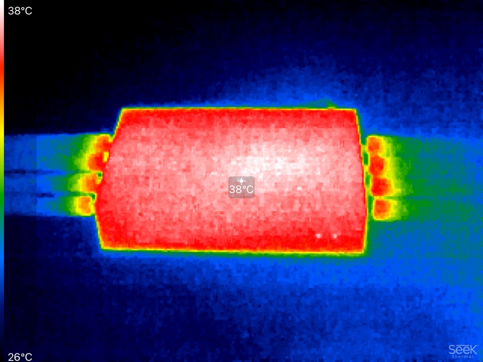
not on the wifi chips, there are only 2 pads in the kit…anyway my temp is always below 50°c and my fan never start…or it starts but I never hear it even though it’s 1 meter away from my head
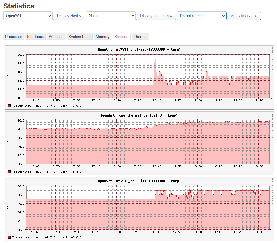
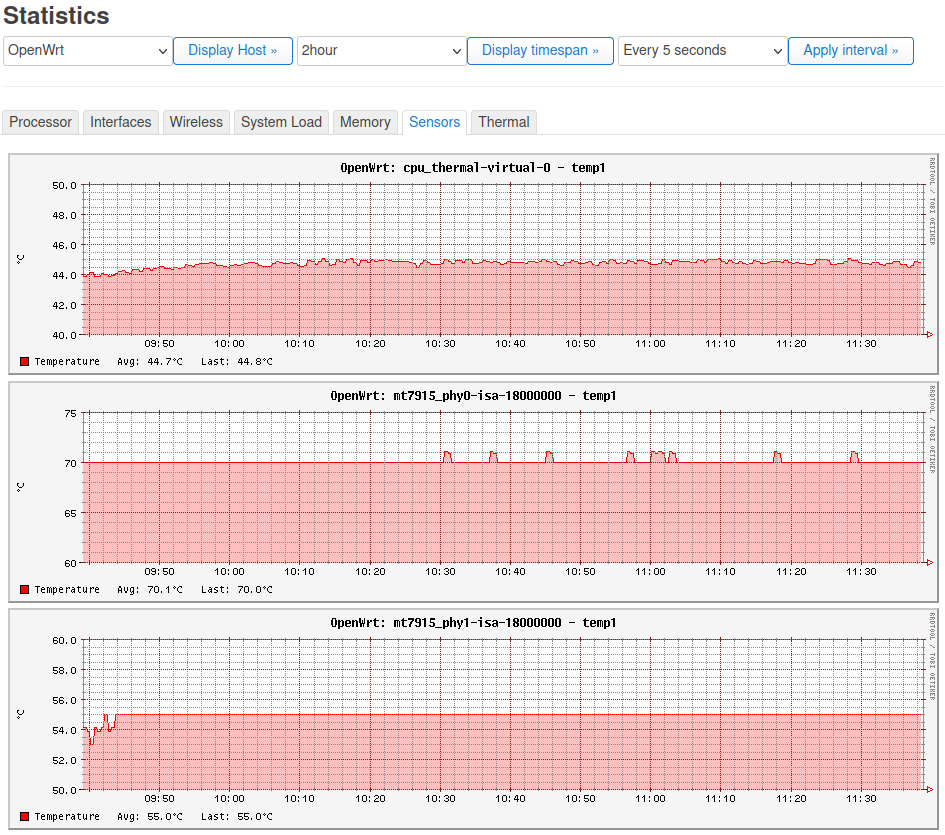
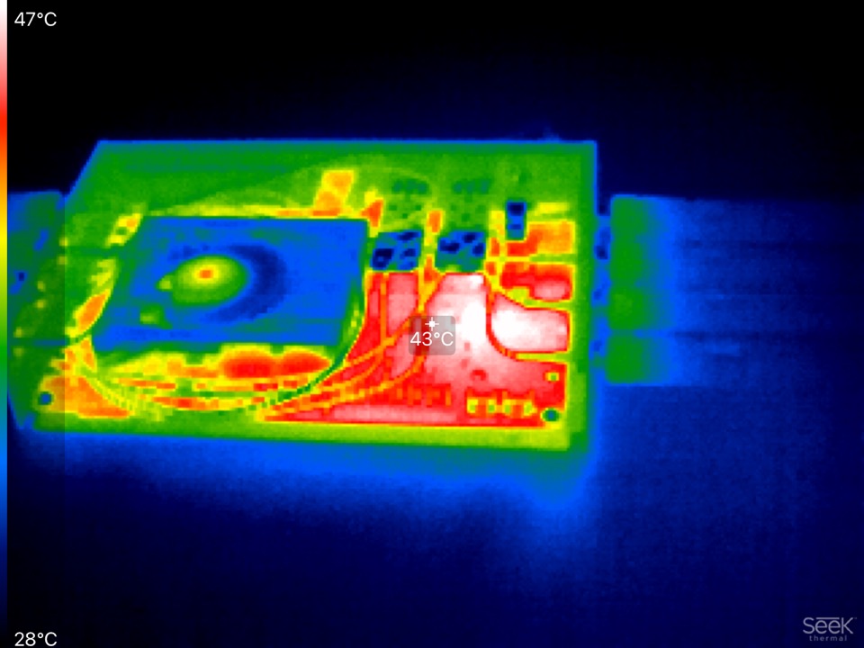
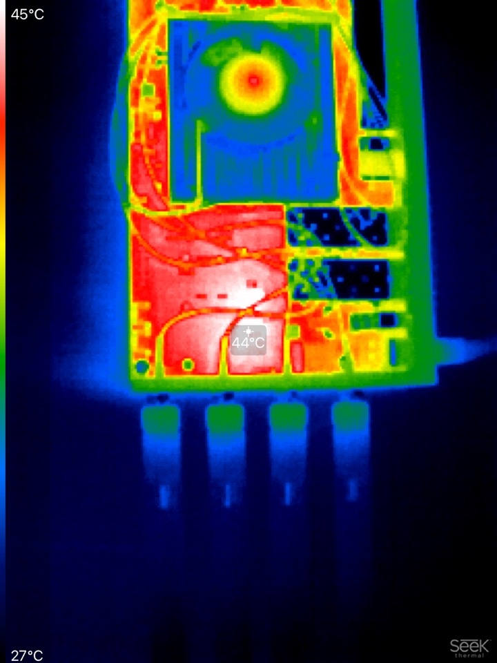
as you can see below, even with no thermal pad, and no contact between the wifi chips and the radiator, the temp never reach 50°c, My office is actually at 20°c
Ok.
I have put thermal pads over each chip under the official fan.
Cpu is running with a stable 44/45 º C.
Mt7915_phy0 shows a wrong temperature, but I can live with it
I think it’s a shame that more conservative defaults are not applied since the case was fairly warm to the touch and could have damaged my system eventually… in other words: out of the box configs should not self-destruct the router
Sorry, i made a mistake when upstreaming the r3 thermal part dts due to my 3rd party pwm was not working with r3.
But you should be aware that mainline software support is done by only a few people,mainly daniel (also openwrt),wifi/hw offloading from lorenzo and some basic parts from me. These are development boards
Argh, sorry for my harsh word actually, “shame” is a bit too strong in this context, I should have used “pity”. If you show me how to modify the dts, I’d be happy to PR the changes to OpenWRT as penitence
Thanks Frank and others to maintain/fix those systems, I totally appreciate the efforts… I bought that board, so at least, I hope that helped somehow
because of looking for a new PWM fan, I also thought about a new heatsink … . I know there is a fan for R3 but I may want to work with thermal paste. At the end it could be that I create a fansink which covers the whole area including SFP and 4G cellular modem. But this is just a dream…
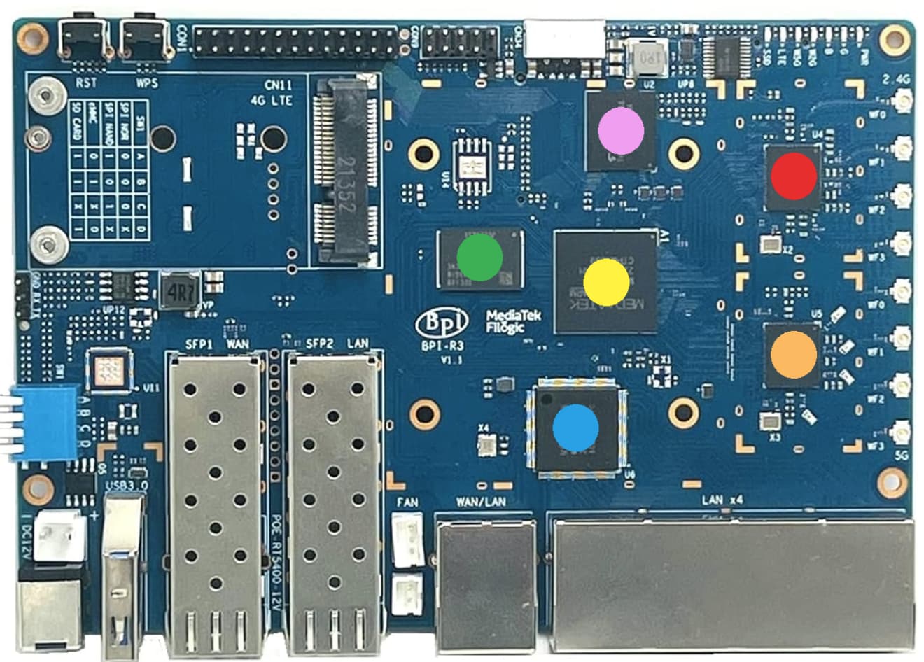
Anyway, I tried to measure more exactly the chips height beneath the heatsink. I still have no digital caliper. But I got the information from internet and from a “piece of paper measurement”.
I know it sounds crazy, but after one day of thinking (How could I find something in my room that could measure in 0.1 mm steps), I realized and find out, that a piece of paper (HP Premium 90g/m^2) has 0.12 mm thickness . And because of the plain surface of the chips it is possible to use a ruler to get the differences between package heights.
YES, crazy!
The measurement results matches really good with the information from internet.
These is the summary:
The minimal thermal pad thickness is 0,5 mm (MT7531AE blue). After covering the chip packages surface with thermal pads, the heights should be 2,1 mm at all chips.
If something is wrong (heights, package, dimension), please write back to me!
Finding the dimensions of the different chip packages was not easy. It would be good if Banana pi could upload this data to the wiki.
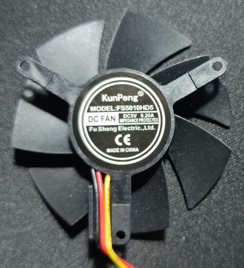
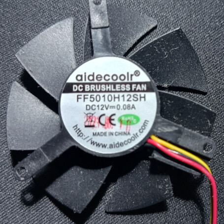
I learned some things about my fan(s) and frank’s post at R4 topic pushed me a bit:
First of all, I learnd that not only the PWM signal on the board is importand. I learnd that a PWM fan has microships inside which can effect the result.
I have two fans. This are my results overview with 5V and 12V:
As I understood, the recommendation for peak-cpu temp of the MediaTek MT7986 is <= 85°C.
So I don’t understand the limits of 115 and 120°C.
Shouldn’t the device already switch itself off if the CPU temperature rises above 90°C?
The 115/120°C is for emergecy switch off. But these shoild not be hanfled with fan like post above. Fan imho should only be used with temperatures below 100°C.
Hello. I’ve been trying to find the original 5V fan or a similar one (without a heatsink) for the BPI R3, but I haven’t been able to find anything. Do you know where to get one?
Recently switched from Open-WRT to Gargoyle-Router firmware, which is based on Open-Wrt.
The router has been working smoothly. Here are new things I learned as I was setting up a PWM
fan on Gargoyle. Bpi-R3 on Open-Wrt has 5 trip points, 0 is reserved for critical and
1 is reserved for Hot, 2,3,4 can be active. Here are the changes I made:
#  Set critical trip point at 95°C on thermal_zone0
# echo "critical" > /sys/class/thermal/thermal_zone0/trip_point_0_type
echo 95000 > /sys/class/thermal/thermal_zone0/trip_point_0_temp

# Set Hot trip point at 75°C on thermal_zone0
# echo "hot" > /sys/class/thermal/thermal_zone0/trip_point_1_type
echo 75000 > /sys/class/thermal/thermal_zone0/trip_point_1_temp
echo 5000 > /sys/class/thermal/thermal_zone0/trip_point_1_hyst

# Set active trip point at 49°C on thermal_zone0
# echo "active" > /sys/class/thermal/thermal_zone0/trip_point_2_type
echo 49000 > /sys/class/thermal/thermal_zone0/trip_point_2_temp
echo 2500 > /sys/class/thermal/thermal_zone0/trip_point_2_hyst

# Set active trip point at 59°C on thermal_zone0
# echo "active" > /sys/class/thermal/thermal_zone0/trip_point_3_type
echo 59000 > /sys/class/thermal/thermal_zone0/trip_point_3_temp
echo 2500 > /sys/class/thermal/thermal_zone0/trip_point_3_hyst

# Set active trip point at 69°C on thermal_zone0
# echo "active" > /sys/class/thermal/thermal_zone0/trip_point_4_type
echo 69000 > /sys/class/thermal/thermal_zone0/trip_point_4_temp
echo 2500 > /sys/class/thermal/thermal_zone0/trip_point_4_hyst

exit 0
Edit:
Note1: 3-Pin/Lead PWM fans will not work because these fans do not have PWM signal wire,
the third wire on these fans is speed/tachometer wire.
Note2: Make sure to use 4Pin PWM fan. Since CN23 connector on BPi-R3 is not 4 pin connector, you will need to modify the 4pin/4lead fan to only use 3 Pins/leads. You do not need the 3rd lead in 4 pin PWM fan, which is speed/tachometer signal lead, securely tape it. Instead Connect the 4th lead of the PWM fan, which is the PWM signal wire, to the third signal pin of “CN23 PWM Fan 3Pin PH-JST connector” on the BPi-R3 PCB.